
NREMT Skillset/Setup for ALS
| Equipment | EMS Jump Bag Endotracheal Tube Set Intravenous Fluids Intravenous Tubing |
|---|---|
| Acting roles | EMR EMT emergency medical responder emergency medical technician paramedic |
| Body systems | nervous system circulatory system muscular system skeletal system |
| Body parts | abdomen arm(s) chest ears eyes feet finger hands head leg(s) lower extremities mouth neck nose pupil thorax toe upper extremities |
Training in setting up ALS systems for Paramedics is included in this California-based EMT program as it is often required in the field and is within scope of practice of EMTs working under the supervision of a Paramedic or nurse. It is not required for skills verification for California Registration.[1]
Skills include setting up an ET tube, setting up and monitoring intravenous fluids, and applying EKG leads.
ET Tube Assembly
[edit | edit source]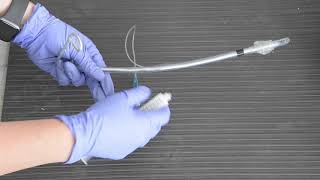
The EndoTracheal Tube (or ET tube) is an airway adjunct that provides both a protected opening into the airway as well as a degree of aspiration protection. Placement of an ET tube (called endotracheal intubation) is outside of the scope of practice for EMTs, but you may be called upon in the field to prepare the ET tube and an intubation kit for a Paramedic, and as such should be familiar with the components and assembly.
To assemble the ET Tube:
- Select the requested size of ET tube. For pediatric patients this will likely range from 3.0/3.5 mm for neonates up to 7.0/7.5 mm in older children, and somewhere between 6.5 to 8.5 mm for adults. The size should be listed on the package
- Don gloves, and open the package with aseptic technique and lay out with a 10 cc syringe on a clean (preferably sterile) surface
- Insert the stylet to, but not past, the side opening at the tip of the ET tube which is known as "Murphy's Eye" and bend the back end of the stylet to ensure it does not advance further during use. Some ET tubes come preassembled with the stylet, but verify that the tip of the stylet is not past Murphy's Eye.
- Test the cuff. Fill a 10 cc Luer lock syringe with air, and attach to the cuff inflation port at the proximal end of the ET tube. Inflate the cuff with 10 cc of air and confirm that the cuff inflates and the external bladder indicating inflation also inflates.
- Deflate the cuff, and lay out the tube for the Paramedic with their intubation kit.
The Intubation kit should include:
- An appropriate size laryngoscope blade MAC, Miller, or combination blade, with a functioning light source
- Age appropriate BVM with a reservoir and needed attachments to ventilate the patient before and after the procedure
- Suction equipment to clear vomitus, secretions, or foreign bodies
- Tape or commercially available "tube holders" to maintain appropriate ET position
- Gloves, mask, and goggles as personal protective equipment
Ventilating the Intubated Patient
[edit | edit source]You will also be called upon to ventilate patients who have been intubated. The connector that sits outside the patient's mouth is the same standard diameter as the mask portion of the Bag Valve Mask, so may be directly connected to the Bag Valve. To ventilate:
- Stabilize. It is essential that the ET tube not be pulled out or pushed further in to the airway, and as such, in addition to any applied tape or tube stabilizers, the tube should be stabilized manually while attaching the bag valve or providing breaths.
- Ventilate. Ventilation with the BVM on an ET tube is delivered every 6 seconds. It is particularly important to ventilate smoothly as forceful ventilations can more easily cause overinflation injuries.
- Monitor. Note the insertion depth of the ET tube from the markings on the side, and ensure this does not change. Check for adequate and symmetric chest rise, listen for bilateral breath sounds. Recognizing the signs of a dislodged or misplaced tube is a lifesaving skill.
Setup and Monitoring IV Fluids
[edit | edit source]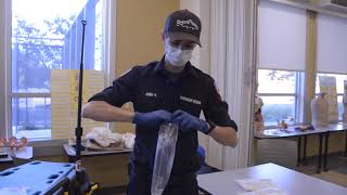
Intravenous (IV) Setup and monitoring is included in this California-based EMT program as it is commonly required skill in the field for EMTs supporting paramedics. It is not required for National NREMT registration or skills verification for California Registration. In California, the State EMSA allows EMT's to transport patient with an established IV as long as there isn't any medication in the IV bag. If patient has an IV that is administering a medication a nurse must accompany the patient as EMT's cannot transport a patient with medication in the IV fluid or as part of a piggyback system, (a second IV flowing into the primary IV bag). Follow your state and county protocols governing scope of practice.
IV therapy is the infusion of fluid directly into the venous circulation of a patient, usually via a cannula. In the prehospital setting the paramedic or nurse on scene will determine when intravenous fluids are required and may place intravenous (IV) cannulas. There are various indications for the administration of fluid in the prehospital setting such as replacement of electrolytes or restoration of blood volume secondary to hemorrhage or dehydration.
Setting up
[edit | edit source]As an EMT you may be called upon to prepare an IV bag for a paramedic. This consists of attaching the IV tubing to the bag (spiking), and flushing the tubing to prime it. IV tubing must be primed with IV solution to remove air from the tubing to prevent air from entering the circulatory system. An air embolism is a potential complication of IV therapy and can enter a patient’s blood system through cut tubing, unprimed IV tubing, access ports, and drip chambers with too little fluid.
- Introduce yourself to the patient as part of the team. The paramedic will explain the procedure of placing the IV cannula to the patient and gain their consent.
- Check the "Five Rights" of delivering medications
- Right Patient: The paramedic or nurse on scene will provide medical direction on the need for IV fluids for a given patient
- Right Drug: Many IV bags look identical, ensure that you have chosen the specified bag: 0.9% Normal Saline (NS, 0.9NaCl, or NSS) is one of the most common IV fluids for volume replacement in hemorrhage, vomiting, diarrhea, hemorrhage, drainage from GI suction, metabolic acidosis, or shock. Lactated Ringers (LR) which is the most similar to blood plasma is often used in extensive burns and trauma patients suffering from acute blood loss. Dextrose 5% (D5 or D5W) and "half normal saline" (0.45NS) may also be called for.
- Right Dosage: Choose the the appropriate drip set. In the prehospital there are two drip sets used, 60 drops (micro drip) for drug administration and 10 drops (macro drip) for fluid support. If not specified, macro drip is assumed.
- Right Route: Intra Venous Administration (IV)
- Right Date: Ensure the IV fluids are not expired.
- Remove the outer packing of the bag and hang it up on a drip stand or other device that will be higher than the patient. (Do not do this until you have verified the fluid type. Once the original bag that the IV bag is sealed in has been broached, it cannot be stored. It must be used immediately.) Not all IV bags have this outer packaging. Be familiar with the brand your organization uses.
- Inspect the bag for any cloudiness or particulate matter present in the fluid and inspect the injection port and the spike port. Do not use the bag if impurities are present or there is damage to the ports.
Spiking:
- Perform hand hygiene and don appropriate PPE.
- Gather supplies. You will need sterile IV solution, primary IV tubing, time label, change label, and alcohol swab.
- Verify the IV solution to be used is: a) The proper solution b) Clean, without particulate matter c) Not outdated d) Not leaking e) Warmed or cooled as indicated
- Select the proper administration set: Primary IV tubing can be macro-drip or micro-drip tubing. a) Macro drip chamber for trauma b) Micro drip chamber for medical conditions and drug administration
- Prepare the IV bag and administration set using an aseptic technique to prevent contamination.
- Remove IV bag from its protective envelope and gently squeeze to detect any punctures or leakage.
- Steady the port of the IV bag with one hand, and remove the protective cap by pulling smoothly to the right to keep it sterile.
- Remove the IV tubing from its protective wrapping or box
- Move the roller clamp about 3 cm below the drip chamber and close the clamp.
- Remove the protective cover on the IV solution port and keep sterile. Remove the protective cover on the IV tubing spike. Be careful and do not contaminate the spike.
- Invert the IV bag.
- Without contaminating the solution port, carefully insert the IV tubing spike into the port, gently pushing and twisting.
- Hang bag on IV pole. The IV bag should be approximately one meter above the IV insertion site.
Flushing:
- Invert all access ports and backcheck valve to prevent air bubbles remaining in the line during flush.
- Fill the drip chamber one-third to one-half full by gently squeezing the chamber. Remove protective cover on the end of the tubing and keep sterile. Filling the drip chamber prevents air from entering the IV tubing.
- With distal end of tubing over a basin or sink, slowly open roller clamp to prime the IV tubing. Invert backcheck valve and ports as the fluid passes through the tubing. Tap gently to remove air and to fill with fluid. Inverting and tapping the access ports and backcheck valve helps displace and remove air when priming the IV tubing.
- Once IV tubing is primed, check the entire length of tubing to ensure no air bubbles are present. This step confirms that air is out of the IV tubing.
- Close roller clamp. Cover end with sterile dead-ender or sterile protective cover. Hang tubing on IV pole to prevent from touching the ground. Keep the distal end sterile prior to connecting IV to patient.
- Label tubing and IV bag with date, time, and initials.
- Perform hand hygiene.
Depending on the EMS system, you may be required to attach an extension tubing to the end of the administration set. Extension sets come in a variety of lengths and have additional injection ports on them. Once an IV has been established it provides easy access to change out the original IV bag and administration set to something else without disturbing the IV injection site. Add an extension by:
- Open a sterile extension set and note the male and female capped ends
- Uncap the female Luer end, remove the protective cap from the end of the drip set line (a male Luer connector), and fasten together without allowing any contamination.
- Flush the extension similarly to the drip set.
Setting the drip rate
[edit | edit source]The drip rate refers to the number of drops of fluid that enter the drip chamber each minute. The drip rate is set manually using the slide clamp, and determines the speed at which the fluid is infused into the patient. In California, it is not within scope of practice for EMTs to prescribe the drip rate, but they may adjust the slide clamp to maintain the specified drip rate. To determine and adjust the drip rate:
- Count the number of drips in a 15 second period, multiply by 4, that is your current drip rate (drips per minute)
- Adjust the slide clamp either tighter (to slow the drips) or looser (to increase the rate), re-count and adjust until the prescribed drip rate is achieved.
Complications to Observe and Possible correction to take
[edit | edit source]If, without an adjustment of the slide clamp, the drip in the chamber stops running, or starts running slower than it should:
- Check to see if the patients extremity is causing the issue. Straighten out their wrist, or in the case of an IV being inserted in the antecubital fossa (the crease of the inside area of the elbow) have the patient straighten their arm out.
- There is the potential a small clot may have formed at the end of the IV catheter inside the patient. DO Not make any attempt to dislodge the clot by opening up the IV drip to full and/or squeeze the bag to force the fluid to force off the clot.
- Check the height of the IV bag. In general, the lower the IV bag is with respect to the patient, the slower the IV will drip, and the higher the IV bag, the faster the IV will drip. Changes in height of the bag as you move the patient from a board to a gurney or into an ambulance and back out will cause your IV drip rate to change and require adjustment.
If it appears that fluid is building up in the tissue around the IV insertion site.
- Turn off the IV with the slide clamp.
If the above techniques to not work, the EMT should turn off the IV to prevent further problems. Once you arrive at receiving facility, notify the medical staff immediately that IV has been turned off.
IV Documentation
[edit | edit source]Documentation of an IV setup should be included in the Patient Care Report (PCR) in the form:
- IV setup does not need to be documented by the EMT. If fluids are running at a prescribed rate, that rate and amount of fluid administered may be documented on a PCR. If an IV is indicated in the prehospital environment, the paramedic or nurse should retain care of the patient.
IV Tips and Tricks
[edit | edit source]- "Drip" is abbreviated by "gtt". IV drip tubing is measured in drops/milliliter. A drip set rated at 10 gtts/mL will provide larger "drops" than one rated at 60 gtts/mL because the 10 drop set only needs 10 "drops" to make 1 mL whereas the 60 drop set needs 60 "drops".
- There are several different drip chambers available. Most common in EMS are macro drip sets (10, 12, or 15 gtts/mL) or micro drip sets (60 gtts/mL). Be sure you are attaching the correct tubing to the IV bag.
Applying EKG Leads
[edit | edit source]Introduction to the Electrocardiogram
[edit | edit source]ECG vs. EKG
[edit | edit source]Electrocardiograms (EKG's or ECG's) are two dimensional representations of the electrical fluctuations of a patient's heart that have been printed onto a piece of paper. The monikers "EKG" and "ECG" may be used interchangeably; EKG comes from the German "Elektrokardiogramm" and is used synonymously with the English "Electrocardiogram". EKG monitors are complicated devices with multiple functions, and fully investigating how a tracing is created involves a significant amount of math that is beyond both the level and the needs of this course.
EKGs in the prehospital setting
[edit | edit source]EKG monitoring is important because it allows providers to gain an in-depth look at the electrical activity in the patient's heart. In the cases of 12-lead EKG interpretation, this monitoring can be used to find blockages within the coronary arteries causing tissue damage or death (otherwise known as myocardial infarction or heart attack). It is therefore important that the EMT be proficient in lead placement for the 4 and 12 lead configurations of the EKG. When asked to place the patient on 4 or 12 lead cardiac monitoring, the EMT should ensure that they have the proper equipment: the appropriate number of electrodes (i.e. stickers or patches), cleaning supplies, and an EKG machine or cardiac monitor. Once the equipment has been gathered, the monitoring may be started.
Skin Preparation
[edit | edit source]Skin preparation is not necessarily required for 4 or 12 lead placement, but proper skin preparation can be the difference between a good reading and one full of artefact. Skin preparation is performed in two steps: the gross decontamination and removal of the outermost skin debris.
Gross decontamination is a fancy way of saying "clean off the skin". Many of the patients contacted in the prehospital environment have the environment on their skin (e.g. feces, sweat, dirt, water, etc.). These environmental factors will preclude the acquisition of a good EKG reading and need to be removed. The majority of these may be removed by alcohol swabs or other solvents and drying, but certain factors such as profuse sweating (diaphoresis) could require alternate measures (such as the application of a betadine/iodine solution that can improve the "stickiness" of the skin to the electrodes). If the patient has chest hair that impedes contact between the electrodes and the skin, the hair should be removed with a razor.
The outermost layer of a person's skin is comprised primarily of dead or mostly dead skin cells and is an effective barrier between the outside world and the underlying tissues. When an EKG is being performed, however, this barrier is actually detrimental as the conductive electrodes will find both less traction on the skin and less electrical conductivity through the dead or dying tissue. To properly prepare the skin, after it has been cleaned scrape the surface of the skin to remove those less conductive cells. This can often be performed with the acetate plastic sheets that the EKG electrodes are initially found on and will also improve the adherence of the electrodes to the underlying skin.
Electrode Placement: 4-lead
[edit | edit source]
The 4 lead is a staple of ALS monitoring. The 4 leads used are the limb leads which are placed on the right and left arms and legs. Alternate placement of the leads such as torso placement is possible and will result in less artefact but less specificity. The placement of the leads is simple and uses color coded wires for the ease of memorization (e.g. white is on the right, smoke/black over fire/red, and sky/white over grass/green) and 4 lead cables often come with two letters found on the head of each cable that denote where the cable should be placed (e.g. RA, LA, RL, LL). Leads placed distally will produce a more clinically significant picture of the patient's cardiac status when a 12 lead is performed but can lead to increased artefact. Each lead should be placed directly on the patient's skin with as much contact as possible and not over a overly bony or muscular area. See Fig. 1 for an example of extremity placement of the limb leads.
A 4 lead will provide 6 different views of the heart known as leads I, II, III, aVR, aVL, and aVF. The last three of these leads (aVR, aVL, and aVF) use an artificial lead known as Wilson's Central Terminal (WCT) to compute their graphs; the "aV" stands for augmented voltage from the right, left, and foot.
Electrode Placement: 12-lead
[edit | edit source]
A 12 lead is performed by placing the initial 4 leads in the correct positions and then an addition 6 leads known as the precordial, or chest, leads. These 10 leads will produce 12 views of the heart, 6 from the limb leads known as I, II, III, aVR, aVL, and aVF and 6 from the precordial leads known as V1-V6. Each lead produces a specific view of the heart and can be grouped by which area of the heart the lead primarily "looks" at.
Septal lead placement
V1- This lead is placed just laterally to the right of the sternum at the 4th intercostal space.
V2-This lead is placed just laterally to the left of the sternum at the 4th intercostal space.
Anterior lead placement
V4- ATTENTION, this lead is placed before V3.This lead is placed along the midclavicular line at the 5th intercostal space.
V3- This lead placement has not true anatomical location, instead it it placed directly between V2 and V4.
Lateral lead placement
V5-This lead is placed along the anterior axillary line at the 5th intercostal space.
V6- This lead is placed along the midaxillary line at the 5th intercostal space.
Anatomy & Physiology
[edit | edit source]How the waveform is produced
[edit | edit source]
The easy explanation is that each pair of conductive electrodes applied to a patient's skin creates a "lead" that measures the difference in electrical potential between the positive and negative electrode of that lead. For EMTs and paramedics, think of the lead as a camera mounted on the positive electrode looking at the negative electrode. Any electrical current travelling towards the camera is shown as a positive deflection while a current travelling away from the camera is seen as negative. Electrical currents travelling perpendicular to the camera are seen as positive deflections (they are moving towards the camera) followed by negative deflections (they are now moving away from the camera (see Fig. 3 for a visual representation of this). The electrodes are placed on the patient's chest and extremities in a way such that the heart is in the "view" of the "cameras"; this allows the lead to view the basic pathway of electricity through the heart from a single angle. As each lead is computed in a different way, each lead therefore looks slightly different as it "looks" at a different area of the heart (this will not be discussed on this page, as it is part of the paramedic curriculum). The different parts of the waveform will be discussed in the next but we will not be going into any significant depth as this page is primarily made for the EMT knowledge skillset.
Parts of the waveform
[edit | edit source]
Fig. 4 shows the waveform produced by the changes in electrical potential in the heart. This tracing is from Lead II, which is the lead most commonly used for rhythm interpretation. Each part of the wave has a name and is associated with some level of electrical movement. This section will discuss point out these waves and give a very brief description of the wave or what it corresponds to in the heart. A more in depth discussion (normal presentation, abnormal presentation, pathophysiology, time intervals, integrated interpretation) will be conducted in the paramedic material.
The isoelectric line is the baseline to which all elevation or depression is compared. It can be found as the long, flat line that indicates a normal resting state of electrical potential in the heart (i.e. the time between heartbeats). The isoelectric line is used to evaluate for ST segment elevation (potential heart attack) and ST segment depression (potential heart injury) among other things. The isoelectric line is not labelled in this image but may be see directly before the P wave.
P wave: The P wave is indicative of atrial depolarization (when the atria receive the impulse to beat). The PR segment (the area from the end of the P wave to the beginning of the QRS complex) is normally found in line with the isoelectric line.
QRS complex: The QRS complex is indicative of ventricular depolarization (when the ventricles receive the impulse to beat) and is made up of three waves, the Q wave, R wave, and S wave. These waves will not fully be discussed in this page as they are used during more in depth analysis of the EKG than an EMT would need to know. The Q wave is simply the first negative deflection after the P wave while the R wave is the first positive deflection after the Q wave. The S wave is the first negative deflection after the R wave. Keep in mind that "deflection" refers to passing the isoelectric line.
T wave: The T wave is indicative of ventricular repolarization. The ST segment (the area from the end of the S wave to the beginning of the T wave) is normally found in line with the isoelectric line.
U wave: The U wave is a rare occurrence to find, and is often not present at all.
Self Assessment
[edit | edit source]- Test your knowledge with this ET Tube quiz
- Practice with the IV Lab Skills lab sheets
- Test your knowledge with this IV Setup quiz
- Test your knowledge with this EKG quiz
References
[edit | edit source]| Authors | Global Surgical Training Challenge |
|---|---|
| License | CC-BY-SA-4.0 |
| Cite as | GSTC (2021–2026). "NREMT Skillset/Setup for ALS". Appropedia. Retrieved July 13, 2026. |