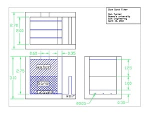
Clean water is necessary for every person on the planet however without access to a means of treating source water, many people go without clean water. A cheap and simple method for treating water from any source would be necessary to provide for people in developing countries. The treatment facility outlined in the excel file and detailed in the provided CAD drawings is relatively inexpensive yet very effective for removing both inorganic and organic contaminants. It should be noted that the actual design has not been tested, however the theory of settling and slow sand filtration is well tested and used throughout the world.
Slow Sand Filtration[edit | edit source]
Settling[edit | edit source]
The design of a settling tank is constrained by the particles which need to be removed. The flow through velocity is equal to the flow rate Q divided by the horizontal surface area (width x height) or
And the detention time of the basin will be equal to the volume divided by the flow rate or:
Since a suspended particle must travel the length and depth of the basin in the time td:
Substituting equation (2) into (4) and then (4) into (3) gives:
This shows that settling basin design is based on flow rate and surface area and is independent of depth. For design purposes, a specified influent rate can be used to determine the surface area necessary to allow particles to settle. Removal of particles will be dependent on the particle diameter given by Stoke's Equation equation below:
Where vt is the terminal settling velocity, p is the particle density, pw is the density of water, d is the diameter and u is the viscosity of water. By substituting the velocity from equation 5 for a given surface area into equation 6, the smallest diameter of removed particles can be found.
This is used in the facility design file to size a basin depending on the diameter of removed particles. The same process was used to design the alternative sieve.
Physical Filtration[edit | edit source]
Physical filtration occurs when a suspended particle is not small enough to fit through the filter bed. As such, the distance between particles in the sand bed acts as a barrier to any particles larger than those particles. Water moves through the filter media due to a hydraulic gradient and the hydraulic conductivity of the least permeable layer (in this case the sand).
Where q is the water flux, K is hydraulic conductivity and J is the hydraulic Gradient. Gives:
Where H1 and H2 are hydraulic heads at locations 1 and 2 and L is the distance between the locations. By substituting the value from equation 2 into equation 3 below we obtain the water velocity through a filter.
Where v is velocity and p is porosity (assumed as 0.25).
Biological Filtration[edit | edit source]
Because the filter is open to sunlight, algae grows and develops a thin layer on the top of the sand filter known as the filter skin. This algae breaks down harmful organics into simpler material which can be further broken down and rendered less harmful to human health. A detailed description of the biological filtration can be found here[3]
Facility Design[edit | edit source]
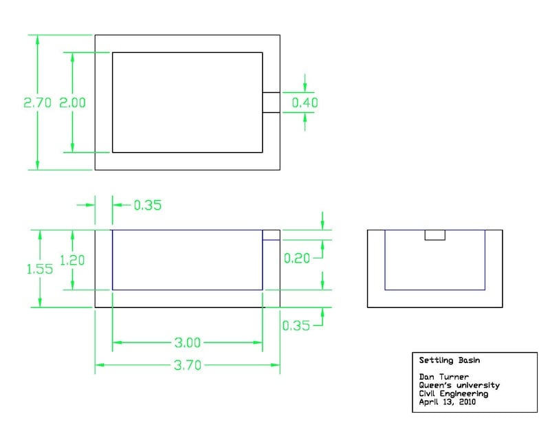
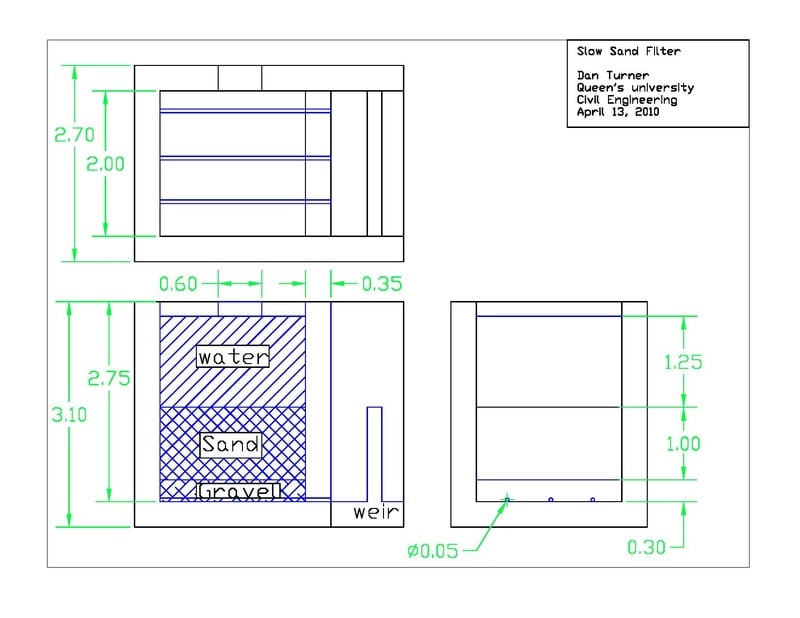
The attached excel file can be used to properly size and dimension a simple, effective and cheap treatment facility for communities of varying size. The design takes the number of people and water consumption for both human and agricultural use into account. The file can be downloaded here:Treatment Facility Design
Many constraints can influence the design of a water treatment facility including the choice of source water. If the only available water source is highly turbid (large number of suspended particles or very murky water) then a settling basin may be required to pre-treat water before it can be filtered effectively. A settling basin design is included where influent flow rate and basin dimensions can be altered to remove the desired diameter of particles. The designed basin does not incorporate automated sludge scrapers (due to expensive and complexity) therefore the basin will require manual draining and scraping. It is assumed that labor is readily available where the facility will be employed. The settling basin effluent weir can then be directed to the filter.
The filter design also has an input velocity and dimension depending on the required amount of water to be filtered per day for the community. Standard depths for the gravel, sand and reservoir layers are included and an effluent weir is used to control the constant head reservoir. A second weir is used to drain excess water from the filter back to the source in order to protect the effluent from re-contamination. The effluent weir also serves to aerate the clean water which increases dissolved oxygen and improves taste. The filter is comprised of a sand layer which acts as a physical and biological filter and a gravel layer which prevents movement of sand into the effluent water. Perforated PVC pipes must be laid into the gravel layer to collect filtered water and pass it to the effluent weir. The filter structure will be made of concrete and a sample concrete mix design is included. The mix design has been tailored to a structure exposed to water. Cost of materials is based on typical Canadian values and can be changed depending on the region. Environmentally, the design is most impacted by the cement use. The treatment facility design does not include methods of collecting source water or distributing/storing water.
Examples of Water Distribution Include:
Alternative Sieve Apparatus[edit | edit source]
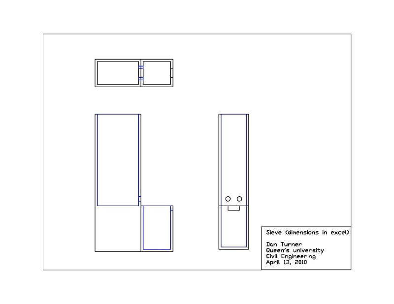
Filter material must have a nominal diameter that corresponds to an adequate hydraulic conductivity. If a sand with a small enough diameter is not available for the filter, a sieve may be used to separate the smaller particles and create an adequate filter material. In areas where standard sieves are not available, a sieve apparatus similar to the settling basin design could be used to separate the smaller particles. The settling velocity of a particle is proportional to the particle diameter and the flow rate across the settling basin. By controlling this rate with basin dimensions and a constant head reservoir, all particles greater than a given diameter will be settled in the basin and smaller particles will remain in the effluent. By removing larger particles in previous basins, particles settled in subsequent sieves will be an adequate size for the filter material. By maintaining a constant head with water that has suspended sand particles, the basin will collect the design diameter which can be collected and used in for the filter material. The sieve design parameters are outlined in the excel file and design drawings are provided.
Filter Maintenance[edit | edit source]
Maintenance of the filter is required. Aside from the necessary concrete cracking maintenance (which is not described here), the filter bed will require periodical maintenance as well. As water is purified by passing through the sand bed, suspended matter and coliforms which attach to the sand particles will clog the filter and reduce flow rate. When flow rate decreases to a level which prevents the necessary amount of water from being filtered, maintenance is required. When this happens, the top 2-3cm of sand should be scraped off and removed from the filter. After subsequent scrapings, the sand level may drop below the required amount (1-1.5m).[1] At this time, more sand should be added to the filter to ensure the length of filtration is adequate. The removed material can be put back into the water upstream to dilute and filter out particles once more.
Design Considerations[edit | edit source]
Materials[edit | edit source]
The slow sand filter is based on hydraulic permeability and head differential. If concrete is not available for the structure of the treatment facility, any material which is less permeable than sand could be used to wall the filter. However it would also have to support the pressure of up to 3 meters of water and 1.5 meters of sand. It may be possible to dig a pit for the filter and line it with a clay (much less permeable than sand) and rely on the soil surrounding the filter to resist the water and sand pressure. However this is much less stable than a concrete structure and may require heavy excavation equipment.
In areas with extreme turbidity, some settling aids may be employed to increase floc size and rate of sedimentation. Chemical additives are likely too expensive for poor communities, however other, natural additives may be employed to accomplish the same purpose. One such material is the Moringa oleifera seed extract.[4] This water-soluble material in suspension can be added to source water before flowing into the settling basin to increase sedimentation of turbid waters.
Environmental Considerations[edit | edit source]
The environmental impacts of this technology come from material choices. Concrete production results in large quantities of CO2 emissions, mostly due to the production of cement. Fine and coarse aggregates may need to be quarried depending on the location. However, blasting may not be required in some developing communities where sand and gravel may be taken from the surrounding area. In this case, the environmental impact and cost are lowered for both the filter and concrete production.
The concrete design used for this treatment system does not use any pozzolans. A pozzolan is used to replace some cement with waste material from an industrial process. Fly ash and soda ash are common materials which can replace some cement and reduce both cost and environmental impact. These materials may not be readily available in developing countries and were not included in the design however they should be used when available.
Climate Considerations[edit | edit source]
The slow sand filter and settling tank design are open to the atmosphere and as such are subject to atmospheric temperature and weather. Therefore the designs cannot be employed in regions where temperatures drop below zero. If the water in the filter freezes it will no longer function, in order to run through low temperatures an expensive, heated building would need to be constructed.
Design Drawbacks[edit | edit source]
The design offered below has been engineered based on water filtration and does not have any structural analysis done. The concrete structure will need to be designed to the standards of the community it is developed for. Foundations may need to be designed based on the soil conditions on site. Steel reinforcement may also need to be installed depending on the structure size.
All costs, both financial and environmental are based on Canadian numbers and as such may not be accurate to the area where the filter will be built. If the treatment plant were to be properly designed for a specific area, research would need to be done to input into the excel sheet provided.
References[edit | edit source]
- ↑ 1.0 1.1 1.2 1.3 "Theory and Practice Of Water and Wastewater Treatment: Engineering Textbook". R.L.Droste. 1997. Copyright John Wiley and Sons Inc.
- ↑ "CIVL 470: Municipal Wastewater Engineering Lecture Notes". B.C.Anderson. 2009.
- ↑ "Slow Sand Filtration"L Huisman and W. Wood. World Health Organization
- ↑ "Bioremediation of turbid surface water using seed extract from moringa oleifera lam. (drumstick) tree". Michael Lea.2010.


