
Humeral Shaft Transverse Fracture Simulator
| Part of | Humeral Fracture Fixation |
|---|---|
| Required by | Self-Assessment Framework Training Logbook |

![]()
This data-driven, gender-specific, easy to print, environmentally friendly, hygienic, and cruelty-free simulator can be locally made to provide the highest fidelity orthopedic surgical simulation training at the lowest cost. Clear cellophane is wrapped around the slightly distracted 3D printed proximal and distal fracture fragments to simulate the soft tissue envelope and permit visual inspection for targeted self-assessment by the learner. The bone models are positioned so the fracture ends are distracted by 2.0 - 3.0 mm but are otherwise properly aligned to simulate a fracture with restored angulation, and rotation.
Materials and Equipment
[edit | edit source]
- 3D Printed Adult Humeral Bone Model #1
- 3D Printed Adult Humeral Bone Model #2

- Clear cellophane
- Optional: Scalpel

- Wood board
- Drill bit
- Hammer
- Nails (Quantity: 4)

- Any powered surgical drill that is compatible with a standard drill bit can be used

- Vise clamps (minimum 2)
- Storage case (not shown)
Assemble and Test Powered Drill
[edit | edit source]
Obtain the following supplies:
- Powered drill (i.e., Arbutus Medical HEX Drill Kit)
- Properly sized drill bit (not shown)

- Follow the drill manufacturer's instructions on how to insert a properly sized drill bit into the drill.
- If using the Arbutus Medical HEX Drill Kit, follow the video instructions to assemble the Arbutus Medical HEX Drill and insert a properly sized drill bit.
- If using the Arbutus Medical HEX Drill Kit, push on the forward drilling direction switch on the right side of the drill for clockwise rotation. NOTE: Different drills have different locations for the switch that controls forward drilling direction.
- Test the drill by squeezing the on/off trigger to confirm that the drill is ready for use. The drill bit tip should be rotating in a clockwise direction when the drill bit tip is pointing away from you.
Set Up of the Humeral Shaft Transverse Fracture Simulator
[edit | edit source]Set Up of the Humeral Shaft Transverse Fracture Simulator
[edit | edit source]- Push a table up against a wall and position the wood board on the table so it is flush with the wall and edge of the table.
- Wrap clear cellophane around the 3D Printed Adult Humeral Bone Models #1 and #2 held by an assistant (click here to watch video).
- Distract the proximal and distal fragments of the wrapped Humeral Shaft Transverse Fracture Simulator by 2 - 3 mm.
- Position the Humeral Shaft Transverse Fracture Simulator so the dome base of each model rests on the wood board to support the simulator, the fracture fragments are slightly distracted by 2-3 mm, and the vise attachment of each model is set up against the edge of the wood board.
- Use any powered drill compatible with the properly sized drill bit to drill two holes in the vise attachment of each bone model (click here to see photo).
- Drill the holes into the center of the side of the wood board to minimize splintering of the wood board.
- Insert two nails through the holes of each vise attachment and into the side of the wood board to secure each fracture fragment to the wood board and prevent displacement of the bone model during drilling (click here to see photo).
- Use a hammer or any suitable heavy implement to apply mechanical force to insert the nails into the drilled holes of the vise attachment and the side of the wood board (click here to see photo).
- The Humeral Shaft Transverse Fracture Simulator simulates the right humerus of a patient in a supine position. Confirm that the simulator is properly oriented by looking at the two semi-engraved drilling direction arrows on the base of each model (click here to see photo). The drilling direction arrows of both models should be pointing in a lateral-to-medial direction.
- Push on each model near the fracture line in a lateral-to-medial and anterior-to-posterior direction to verify stability before drilling. If the model moves, insert an additional nail in the vise attachment and wood board to prevent movement of the model.
- Remove one nail from the vise attachment of the distal fragment to permit displacement of the fracture before using the rods and Schanz screws to reduce and compress the fracture during simulation training.
Optional: Using Vise Clamps to Set Up the Humeral Shaft Transverse Fracture Simulator
[edit | edit source]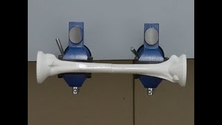
- If available, position two vise clamps on a table approximately 17.5 cm apart and open the jaws of each vise clamp.
- Wrap clear cellophane around the 3D Printed Adult Humeral Bone Models #1 and #2 held by an assistant.
- Distract the proximal and distal fragments of the wrapped Humeral Shaft Transverse Fracture Simulator by 2 - 3 mm.
- Use the two vise attachments of the simulator to gauge the distance between the left and right vise clamps. Adjust the position of the vise clamps and then secure each vise clamp to the table.
- Place Model #1 (the proximal fragment) into the left vise clamp and Model #2 (the distal fragment) into the right vise clamp. Each vise attachment should be centered on the threaded screw that connects the jaws of a vise clamp.
- Turn each vise handle until the jaws are clamping each model securely. Confirm that the proximal and distal fragments of the simulator are distracted by 2 - 3 mm but are otherwise properly aligned to simulate a fracture with restored angulation, and rotation.
- The Humeral Shaft Transverse Fracture Simulator simulates the right humerus of a patient in a supine position. Confirm that the simulator is properly oriented by looking at the two semi-engraved drilling direction arrows on the base of each model (click here to see photo). The drilling direction arrows of both models should be pointing in a lateral-to-medial direction.
- Push on each model near the fracture line in a lateral-to-medial and anterior-to-posterior direction to verify stability before drilling. If the model moves, re-tighten all the handles of each vise clamp for a stronger grip.
Acknowledgements
[edit | edit source]This work is funded by a grant from the Intuitive Foundation. Any research, findings, conclusions, or recommendations expressed in this work are those of the author(s), and not of the Intuitive Foundation.
References
[edit | edit source]- ↑ Arbutus Medical. Hex Drill Kit - Orthopedic Surgical Drill [Internet]. Arbutus Medical. Arbutus Medical; 2021 [cited 2021 Nov 28]. Available from: https://arbutusmedical.com/drillcover-hex/.
| Authors | |
|---|---|
| License | CC-BY-SA-4.0 |
| Cite as | Medical Makers (2022–2025). "Humeral Shaft Transverse Fracture Simulator". Appropedia. Retrieved July 31, 2026. |