This page contains the documentation for my Engr305 appropriate technology class project. The project is to build a working model of a Pulser pump. There is limited but growing documentation of how the thing actually works. The mission of my project is to experiment with the mechanism and add my findings to the body of knowledge developing around this astonishing device. As an engineering student, this is an opportunity for me to practice the design process, as well as an opportunity to experiment with a technology that is not widely used.
The pulser pump functions by drawing aerated water down into the bottom of the u-shaped structure and catching the air in the bottom of the U; this air becomes pressurized as it accumulates by the weight of the water columns on either side and is thus able to force its way up a smaller pipe that projects a small distance into the U, carrying some water from the chamber up with it to a higher elevation than it entered the structure(two-phase flow). My project will shed light on some of the complexities of the pulser pump functions and hopefully aid future experimenters in producing an efficient product. A product that will be able to turn large flow in relatively flat waterways into the head that can be used for irrigation, Microhydro, and stored for a myriad of other uses. Pulser pumps could be revolutionary in that they require little to no maintenance and zero input energy after setup.
Literature Review[edit | edit source]
The Trompe[edit | edit source]
The trompe, sometimes spelled trombe, is a mechanism for drawing mixing air with water and pressurizing the air. A tube of varying length is installed perpendicular to the surface of water with its opening just below the surface. This arrangement causes water and air to be alternately pulled down into the tube, first the water by gravity then air by the vacuum created when a small amount of water descends into the tube. The switch happens when the water immediately surrounding the pipe entrance flows in, because the surface height there takes time to equalize back up to the surface height of the rest of the water. When the mixture of water and air descends down the pipe the air becomes pressurized by the weight of the water. (Hunt 2010)
The Air Lift Pump[edit | edit source]
When air is mixed with water under pressure it wants to expand; given a small enough outlet water can be pushed up said outlet by the expansion of that air. This mechanism is called Two-Phase Flow, and it drives the air lift pump. The specific type of two phase flow necessary to lift fluid upward is Slug/Plug flow (Stepanoff 1965). Two phase flow is described in more depth here.
General mechanics of head and flow[edit | edit source]
The principles of head and flow are integral to the function of pulser pumps.
Head[edit | edit source]
When a fluid is elevated, it has a gravitational potential energy. This potential is called head or sometimes pressure head, as it is a way of quantifying the amount of pressure in a water column.It is typically measure in meters or feet of height, as the distance from the source to where it is being deposited is the dimension in which the mass of the fluid is being acted upon by gravity. (Sullivan 1975) (more)
Flow[edit | edit source]
Flow is a measure of volume with respect to time. It is often measured in gallons per minute, though any measure of volume per time is suitable. (Grafman 2010)
The Pulser Pump[edit | edit source]
Brian White, among others, has built a pump that is the union of a trompe and an air lift pump. It uses the trompe to take flow in a stream and pressurize air in the water in a chamber below, this pressurized air then pushes a small amount of the water up though a smaller outtake to a higher elevation than the top of the trompe. The mechanics of the pump are well documented here,this page is devoted more to my design process.(White 2008)
Criteria[edit | edit source]
ED: INTRODUCE THIS CRITERIA SECTION. These are the criteria by which the success of the project will be judged.
| Criterion | Weight | Constraints |
|---|---|---|
| Cost | 10 | Maximum budget of $100. |
| Concept Demonstration | 10 | Must demonstrate that the concept is sound. |
| Level of Embedded Energy | 9 | The more parts bought used the better. |
| Efficiency | 5 | The higher the flow and the higher it's pumped, the better. |
Budget[edit | edit source]
| Item | Quantity | Total Cost($) |
|---|---|---|
| 4" pvc | 10 ft | 10 |
| plastic trashcan | 1 | free |
| 45 elbow | 3 | 6 |
| E600 PVC Glue | 1 | 6.48 |
| 3/4" PVC | 15 ft | free |
| Duct Tape | 1 roll | 5 |
| gorilla tape | 1 | 4 |
| 3/4" rubber washer | 1 | .89 |
| large plastic tupperware | 1 | free |
Total Project Cost=$32.37
Design[edit | edit source]
Process[edit | edit source]
I spent far too little time in design. I started with some pointers that Brian White gave me and jumped into the physical structure design before I completely understood the math involved. The major flaw in the project is that it was designed to accommodate the energies in a pump for legitimate application and not designed to be a demonstrative model. Despite this major fallback the design meets the three top criteria very well.
Cost: See the budget for details, but note that the pump is built almost entirely from used and therefore free or extremely cheep parts.
Concept Demonstration: However effective/efficient, this design uses elevated water columns and aerated flow to generate a two phase flow regime which brings water higher than it is introduced.
Level of Embedded Energy: This is where the project really stands out; I'm proud of the DIY, creatively driven, see what comes out of the salvage yard method I employed for this project. It was very inexpensive in both energy and money.
It's not the most rigorous experimentation but it was fun and I hope people who read this see that they can have an adventure with science for a small amount of dollars and a few (or many) trips to the salvage yard.
Physical System[edit | edit source]
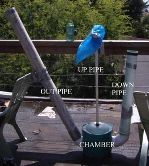
The structure consists of four main parts,
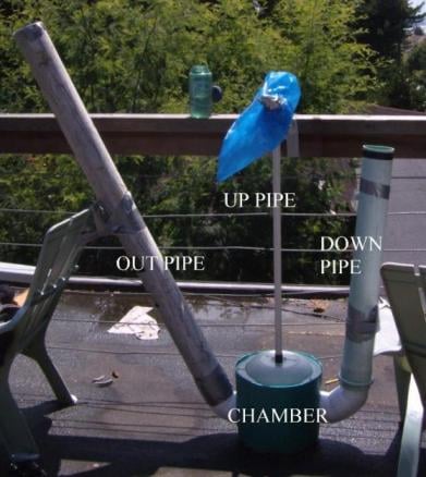
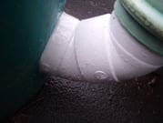
The down pipe- 4" diameter, brings air and water down into the chamber, provides head to pressurize air in the chamber. Joins to the chamber with two 45 degree elbows
The out pipe- 4" diameter, brings water back up from the chamber sans-air bubbles, provides head to pressurize air in the chamber. Joins to the chamber with a 45 degree elbow
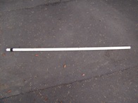
The up pipe- ¾" diameter, two phase flow regime occurs in this pipe bringing water to the top, three lengths were used 49", 41", and 33". 1½" above the bottom end is wrapped with a strip of gorilla tape to aid the seal with the chamber (air pressure is a wily escape artist).
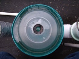
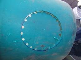
The chamber- The bottom of an old plastic waste bin I salvaged glued to an old large Tupperware I had lying around. The top hole in the chamber has a ¾" rubber gasket glued over it so that I could test different lengths of "up" pipe. Two other holes I made by tracing my 4" pipe onto the side of the bin, drilling small holes on that circle and then finishing the cut with the handsaw in my multi-tool. The down and out pipes are joined to these holes with E600 multi-purpose adhesive.
Wanna See a Video?[edit | edit source]
http://www.youtube.com/watch?v=LungrknZtic
Testing/Troubleshooting[edit | edit source]
As I mentioned before this model was built to accommodate the energies in a real system, more simply, I did not have the amount of flow necessary to carry the quantity of air I needed. My hose flows at.56 L/s and in a 4" pipe that isn't fast enough to bring air bubbles through the chamber in consistently high quantities necessary for the pump to work. To compensate for this problem I sprayed the hose down a ¾" pipe placed in the in pipe (I call this my cheater pipe, it increased air flow into the pump drastically). I know that it in no way mimics the natural system of a trompe but without a creek to stick my pump in I had to get creative. The cheater pipe is 30 in. long. I was able to measure the output by collecting it in a bag taped to the top of the pump (see the picture above).After six sets of flow tests with the above flow rate I compiled the results in the table below.
table key: UP=height of the up pipe(in.),WC=height of the right hand water column(in.),CP=was the cheater pipe used,FR=the flow rate out of the up pipe(mL/min..
Flow Rates w/ Varied Input
| UP | WC | CP | FR |
|---|---|---|---|
| 49 | 24 | no | 4.5 |
| 49 | 18 | yes | 7.5 |
| 41 | 24 | no | 8.0 |
| 41 | 18 | yes | 49 |
| 33 | 24 | no | 36 |
| 33 | 18 | yes | 110 |
note: It seems to me that the obvious correlation of increased pumping height decreasing flow rate is far overshadowed by the extra aeration given by the cheater pipe, leading me to believe that a trompe that provided maximum air flow would yield the best results.
Conclusions/Records[edit | edit source]
variations and consistencies[edit | edit source]
In my testing I varied the height of the up pipe, and the the manner in which air was delivered to the chamber. The flow rate of water was maintained throughout, but the cheater pipe allowed the air to flow in faster. The volume of the compression chamber (the volume of air in the chamber fluctuates around this number) was a constant 267 cubic inches, and the extension of the up pipe into the chamber was 1 and 1/4 inches.
Interpretation[edit | edit source]
The pump rate is inversely proportional to the height water is being pumped to and directly proportional to the flow rate of air in the water and height of the pressurizing water columns. In order for slug/plug flow to
References[edit | edit source]
Sullivan, J. A. (1975) "Head and Pressure"
Fluid Power: Theory and Applications p. 58,59
Reston Publishing Company, Inc. Reston, Virginia 22090
Cheremisiniff, N. P. (1981) "properties of fluids","principles of fluid flow"
Fluid Flow: Pumps, Pipes and Channels p. 43-47, 163-166
Ann Arbor Science Publishers Inc., Ann Arbor, Michigan 48106
Stepanoff, A. J. (1965) "flow of gas-liquid mixtures"
Pumps and Blowers, Two Phase Flow p 275-280
John Wiley & Sons, Inc.
Hunt, J. R. (2010) "Harness Hydro Power with a Trompe"
Mother Earth News, 02/13/10
Lonny Graffman (2010) "general mechanics of flow and head" Personal Correspondence
White, B. (2008) "Pulser Pump" Appropedia, 02/7/10
