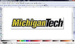
If any one knows an easier way of doing this - please add in below:
Software needed[edit | edit source]
- Inkscape - An open source vector graphics editor, with capabilities similar to Illustrator, CorelDraw, or Xara X, using the W3C standard Scalable Vector Graphics (SVG) file format.
- OpenSCAD - The programmer's solid 3D CAD modeler
- Blender - A more flexible 3D design (not CAD) modeling software. This option is much more likely to successfully import your drawing and allow you to recognize faces, but may not result in dimensionally accurate or 3D printable STLs (it takes some practice, but it is possible).
Convert Image to Vector Graphics[edit | edit source]
- Get a 2D image and open it in Inkscape (or draw it in Inkscape)
- Convert it to a path (if it worked you should see a bunch of grey squares)
- If it is a found image go to Path --> Trace bitmap - shift+Alt+B
- (if you drew it Path--> Object to path or click Shift+Ctrl+C)
- Select every node -- go to Edit --> Select all or Ctrl+A
- If you want a high resolution (curved lines) then click the far left button "insert new nodes into selected segments" (do this as many times as you like 2 or 3 times gets pretty smooth curves on most images
- Then click the "Make selected segments lines" button - see screenshot (if you can not see the buttons click F2.)
File > Save Asa dxf file.
OpenSCAD[edit | edit source]
- Either save the file into your OpenSCAD directory or move it after you save it
- Start OpenSCAD
- Use the import command in the directory you saved it in. This is easily acheived by dragging the file from the file explorer into the editor window of OpenSCAD. If not on your own computer (e.g. MTU computer use):
import(file="\\\\mtucifs3.iso.mtu.edu\\home\\My Pictures\\filename.dxf", convexity=3);- Convexity is a measure of the number of times a straight line could pass through an edge in your drawing (during a ray trace).
- Then you can use
linear_extrude() - Compile and Render it (F6)
- If you have trouble getting anything to show up, on the menu bar go to
File > Examples > Old > example007.scad. - This Inkscape Add-in is also worth a shot.
- If you have trouble getting anything to show up, on the menu bar go to
- Save as STL for printing: Click Design --> Save as STL (this could take some time depending on how complex your object is)
- Open in your favorite 3D printing software and have a go at printing it
Blender[edit | edit source]
- Start Blender in Modeling mode
- Go to
Edit > Preferences > Add-ons > Import-Export: Import AutoCAD DXF Format (.dxf) - Close the Preferences window.
- Go to
File > Import > AutoCAD DXFand find your file. The sketch will import - you may have to zoom out to find it. - Right-click on the curve and select
Convert to Mesh - The object is now editable. To extrude the image, switch from
Object ModetoEdit Modeusing the drop-down menu on the top left.- Next to that drop down menu are three buttons which allow you to toggle between Vertex, Edge, and Face Selection. Start with Vertex Selection.
- Break the surfaces you would like to extrude into simple geometric shapes. This is particularly important if you have gapes in the middle of your drawing. When Blender creates faces, it interpolates the surface in between all of the vertices/edges selected. This means it will not automatically recognize those holes, and will just fill them in unless they are connected by edges
- To create an edge, select two vertices (Shift-click) and hit the
Fkey. This is a 'Fill' command. - Once you have broken down your surface, start filling in faces. Select a vertex, then Ctrl+Click on another point down the path that you would like to form the boundary of your face. Ctrl+Click selects all vertices between the last two selected vertices, along the shortest path (indicated by the mouse definitions in the bottom bar of the Blender window). Use this to trace out your boundary, then hit the
Fkey. - Once you have completed the creation of your faces, select all the faces using Shift+Click and extrude them using the tool on the left bar.
- See this video for reference.
Alternatives[edit | edit source]
For a real world item, such as a photograph, an alternative is to use a group of images/photographs taken at slightly different angle and with different focus points.
Using the open source software VisualFSM you can convert the collection of images into 3d cloud of point data - which can then be edited by Meshlab for printing. See http://wedidstuff.heavyimage.com/index.php/2013/07/12/open-source-photogrammetry-workflow/ for a tutorial on how to do it. Free cost but not open source: http://www.selva3d.com. Upload your file and it is converted to STL following 3 steps, without need to download any software.


