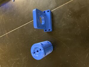
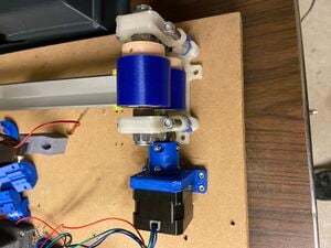
Approximately 30% of printed Polylactic acid (PLA) becomes scrap once printed because facilities don't have the means to recycle it [Insert Citation Here]. PLA, which is made primarily of corn starch, can decompose into CO2 and water if done correctly [1]. In order to recycle the printed PLA, students and faculty members must ship the PLA to a company in order for it to be melted and reused. The purpose behind this project is to design a Recycle bot in order to melt and spool printed PLA for easy accessibility for everyone. This was done by taking the schematics of a previous Recyclebot, analyzing what worked and what didn't work, and make updates and changes to accommodate for our material.
Objective[edit | edit source]
The goal of this project is to take failed 3D prints from previous and ongoing projects, and turn them into usable spools of filament for printing new parts. After the parts are crushed up, they are melted down and extruded in the Recyclebot and spun into new filament spools. The second version of the Industrial Recyclebot is to take the concept created in previous iterations of the project, and output filament at multiple times the current rate of the previous iterations. This revision focuses on outputting more filament, as well as making the entire project affordable and open source so that any end user could recreate and build the robot using a 3D printer, off the shelf parts at a local hardware store, and simple hand and power tools.
Background[edit | edit source]
The Open Source Hardware Enterprise focuses on designing projects that are easy to build in the average home and accessible to the public. We achieve this by considering cost-effectiveness and making sure that as many components as possible can be built in-house. Most of the time this means 3D printing parts from PLA since it is popular and well-supported among hobbyists everywhere. That being the case, the Enterprise has several 3D printers and consumes high amounts of PLA to build prototypes. Because of printer calibration, failed prints, and design revisions, around 30% of the PLA becomes scrap and is placed in a bin for recycling.
The Industrial Recyclebot was developed to reduce waste and save money by turning scrap plastic into full spindles of usable filament. It does this by melting pellets of ground-up plastic, extruding the molten material into a filament, and winding it onto a spindle for later use in 3D printing.
Problem/Opportunity Statement[edit | edit source]
The biggest issue of the original Industrial Recyclebot is the extrusion's output efficiency. It takes approximately five hours to remelt down one pound of PLA. This is what we want to increase significantly. To increase extrusion, a stronger motor is required to continue to push the melted PLA. The auger that compresses the PLA must also be wider in order to reduce the amount of work on the motor. The final issue is a proper cooling system to avoid PLA sticking to itself as it is spun/rotated on the final spindle. The PLA will constantly be touching itself as it is spun to optimize the space on the spool. Automation is also desired, so a member does not have to watch the recycle bot run for the entire duration.
Currently, the enterprise has two different Recycle Bots. The first Recycle Bot is a test of concept, which has an extremely poor output of PLA. The Industrial Recyclebot has an improved system with an increased output of X5 the proof of concept. To fulfill these improvements, the original AC motor is going to be changed to a stepper motor, as the original AC motor speed cannot be controlled accurately. The next change to the Industrial Recyclebot addresses the premelting of the PLA in the piping around the auger bit. To do this, the length of the pipe and auger bit are going to be increased to discourage the heat from the heating elements to creep down the length of the pipe and into the hopper. Because of this change, the hopper design needs to be changed to account for the new pipe length. These new components will be 3D printed, much like the other parts on the robot. Figure 1 shows the Original Industrial Recyclebot layout that will be matched, but the components will need to be optimized. The current design utilizes multiplecontrol boxes to adjust the settings for the heaters.
With our new design, arduinos will be used to allow adjusting of the setting from a single display and a more user friendly interface. These arduinos will also allow the machine to run completely autonomous allowing the user to turn the machine on then guide the initial PLA strand and may leave the room. Many of the components being changed to allow for greater efficiency and reduce the overall cost of the robot by being found in more common sizes and materials, making them easier and cheaper to purchase.
Project Significance[edit | edit source]
Our project would significantly help the entire enterprise by reducing the cost of a product we use everyday. These reduced costs would also benefit the students who come to us to 3D print their designs. With a cheaper way to create prints, the cost reduction we can provide will help students save money. The university would also save money, as we have done 3D printing projects for them in the past. The enterprise has collaborated with recycling plants to spindle grinded plastic pieces in which the Recyclebot was able to respindle, and with the help of 75% recycled and 25% new plastic, the enterprise were the first ones able to accomplish this.
Bill of Material[edit | edit source]
All parts needed to build the Recyclebot Industrial
Tools Needed[edit | edit source]
Basic hand tools and basic power tools are all that is needed for this project. The Recyclebot Industrial can be put together using an assortment of metric allen keys, and a power drill with various sized drill bits. Every screw in this robot uses a hex key to screw the parts into place on the board, mainly socket head cap screws are used. The power drill is used to drill the exit hole for the filament at the end of the barrel, and to drill pilot holes for the screws in the board. No cutting is necessary for this project besides cutting the bottom off a 2 liter soda bottle.
Technical Specifications and Assembly Instructions[edit | edit source]
The technical specifications and assembly instructions can be found under the electrical and mechanical documentation folders in the OSHE google drive in the Recyclebot Industrial v2 project folder. These documents outline where everything is located in the shared drive, as well as the pinnout diagram for the Arduino and the assembly instructions to build the robot. Each part that needs to be printed can also be found in the shared drive under its parent assembly.
References[edit | edit source]
[1] T. Raine, "Reduce, reuse, recycle," Printweek; London, pp. 31–32, 15-Mar-2007.
Fall 2019[edit | edit source]
Much of the Fall of 2019 was spent researching the proper specifications on how to effectively redesign the robot. This research included how to combine each control box into a single Arduino with a unique GUI interface, making the robot easier to control and allowing the user to save custom settings for future use. Other types of research included determining what the best size screw conveyor/ auger bit to use, as one of the goals for this project was to be able to create filament from any type of plastic. This meant that the auger size must increase in order for the robot to be able to process larger sized pellets such as PETG and PLA.
The second part of the Fall of 2019 semester was spent redesigning the hot end of the robot to accept the new auger size and drive motor. The drive motor that was previously used was a large DC motor that had little to no control, and switching to a stepper motor would allow us to control the rate at which the auger pushes the pellets. This, in turn, forced us to create a new hopper as the previous version used a specialty hopper designed for a specific screw conveyor. The redesign in the hopper also allows the user to 3D print the hopper instead of making cuts that are close to impossible to make without specialty equipment. This CAD work will be carried over into the Spring of 2020 where the goal is to have a completed and functioning robot so that testing can commence towards the extrusion of a final product.
Spring 2020[edit | edit source]
Spring of 2020 was focused on finalizing our first design and assembling it with the goal of having basic functionality by the end of the semester. Obviously the campus shutting down due to COVID-19 greatly affected our ability to accomplish that final goal but we still made good progress. As of the end of our ability to work in person, assembly of the entire hot end of the machine's mechanical and electrical elements was almost complete and we had begun verification testing of some basic functions. Our heaters were both able to turn on and we successfully regulated temperature using our Arduino code. For the stepper motors, we created test code and had started to test functionality when spring break started. Obviously we never got back into the lab to finish that verification work. Below is the current state of our build. Below is our current assembly(top) and our heaters running to a desired temp(bottom).
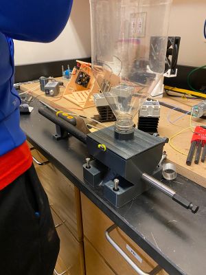
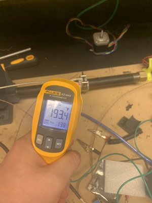
After things moved online our team shifted focus to preparing everything as much as we could so it could easily be picked up by the group next year. The mechanical design was finished in CAD for the entire cold end so we now have a finished design and CAD model for the entire system. On the software side we finished the code so that with minimal work next year verification testing of individual subsystems and whole system testing can resume quickly. The electrical system was documented in detail as well as the why parts were chosen and how they interact. All the parts that are needed to build the Industrial Recycle bot as currently designed as well as where to purchase those parts are laid out in our BOM document. Overall we are very happy with our design that we created and we undershot our expected price we had at the beginning of the year by quite a bit coming in with a cost to build of under $750. Below is the current CAD layout of our design.
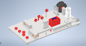
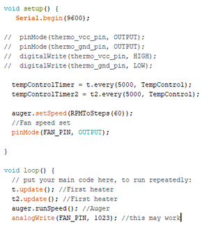
For the next semester of this project, the goal is a complete and functioning machine with a full UI and compatibility with multiple plastic types. Planning has already begun for the creation of a UI for easier user interaction with this system and all code has been designed so it can easily integrate with a UI. Below is our example code running the main loop set to begin testing.
Fall 2020[edit | edit source]
This fall we made significant progress on the development of the Industrial Recycle bot. The full CAD design was completed, including revisions to solve issues that arose in assembly. The main improvements to the design this fall focused on safety. Each moving part that is driven by a motor is covered so that it cannot be touched without removing the cover, this means that the direct pullers and spooling mechanism are enclosed. The components that heat up are also covered to eliminate the risk of burning or starting a fire. The barrel of the robot heats up quickly and to very high temperatures, so covers were designed to keep fingers and objects away from the barrel and heater elements. The second focus of the design changes was to make the Recyclebot visually aesthetic. To do this, all the wires are run under the base board and will meet inside the control box so that no wires are exposed or seen. Below is a picture of each component of the robot bolted to the board in its final position, excluding the cover to the barrel and the control box (wiring still being worked on).
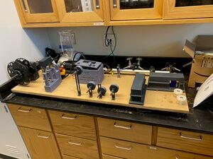
Our final purchasing price was $999 for the initial design, including components that were not used. This price will be reduced for the final design, as the exact components are known. The Recycle bot has a completed CAD design, Codebase, test cases, and documentation. The final assembly with wiring is the only thing left to be completed before it will be ready to begin testing filament production.
Our current code base can be found at https://github.com/OSHE-Github/Recycle-Bot
Next semester the wiring can be completed and the initial testing of the filament can begin. Once we can verify that the hot end produces adequate filament, the cold end can be tested to verify proper spindling and cooling.
Spring 2021[edit | edit source]
This semester the Recyclebot team was replaced completely with Josh Stiebel and Anthony Walter. The first thing we did was figure out how the bot was supposed to function, as it did not have good documentation. After reading through the codebase, reading the Appropedia pages, and examining the robot, we started to work on wiring. Although the previous team stated that the wiring was "halfway done", the wiring had to be overhauled for it to function. The wiring that was done was incorrect. We understand that this was probably because of the COVID-19 pandemic causing limited lab access.
So after spending some time learning about Arduino, RAMPs boards, and solid state relays, the wiring was finished up on the robot. One one of the changes we made was switching out the dc motors with stepper motors, for better control. To do this we had to redesign and reprint the motor mounts to fit the stepper motors, which are currently located on the GitHub. Once all of the components were wired up and the motors were mounted, it was time to work on the code.
Since Recyclebot's wiring was not configured when the code was written, the code did not function. I [Josh] could see what they were trying to do with the code, but it did not work as written. This was fixed by rewriting the code, using the basic structure of the previous code, but with the correct pin numbers, and some other minor changes. Once this was done, the robot seemed to be complete. The code could control each of the elements of the recycle bot, including keeping the temperature steady at a specified temp (Using Bang Bang).
First, we tried testing the bot with PLA pellets, and it kind of worked, but there were 2 considerable problems. The first was that the filament would jam in the nozzle constantly, and it was almost impossible to get a steady flow for any long period of time. The second problem was that once it did extrude some filament, it was so brittle that it could not get around the 90 degree turn at the end of the cooling section. To fix the first problem of jamming we tried to move the augur closer to the end of the pipe, because there was a very sizable gap between the end of the augur and the nozzle. This made it a bit better but it still jammed if left to extrude for even a short period of time. And for the turn, we just removed the turn and are going to move the spool to the end, having it be a straight line. This is where we ended the project for the semester. A future option is the wheels that the filament initially run through could have a larger diameter and width so the filament doesn't have to make as sharp of a turn to prevent it from cracking or falling off of the wheels.
As for the future of the Recyclebot, neither of the two current members, Josh or Anthony, will be working on the project. So I will try and leave as much documentation as I can below for anyone who wishes to continue this project in the fall of 2021.
You can find the pins referenced in the diagram of the ramps board located HERE
The current code can be found HERE
STEPPER MOTOR WIRING:
Each stepper motor should be wired to to the pins next to the axis letters X, Y, or Z. Under it, you should place jumpers to set the step size (currently we put one jumper for each motor, placed on the right, setting a step size of 1/16). On top of the jumpers, should place the stepper motor driver. The little screw on the drivers sets the current. (Jumper is shown in tweezers)
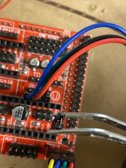
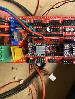
The code below should set up the pins for two stepper motors on the X and Z axis pins of the ramps board.
//x stepper motors

# define X_STEP_PIN 54
# define X_DIR_PIN 55
# define X_ENABLE_PIN 38

//z stepper motors

# define Z_STEP_PIN 46
# define Z_DIR_PIN 48
# define Z_ENABLE_PIN 62

//setup motors using accelstepper library
AccelStepper stepper(1, X_STEP_PIN, X_DIR_PIN);
AccelStepper zstepper(1, Z_STEP_PIN, Z_DIR_PIN);
MAX6675 SETUP: To setup the MAX6675's thermocouple sensors, connect the pins on the sensor to the aux-3 pins on the ramps board (bottom right). Both temp sensors should share the same top 4 pins, gnd, sck, 5v and MISO. To do this, connect the same pins on each of the MAX boards together, and then connect that new wire, to the matching pin on the ramps board. Then each of the CS pins from the MAX6675 should go to a different one of the lower pins (one should connect to D53 and the other to D49).
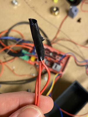
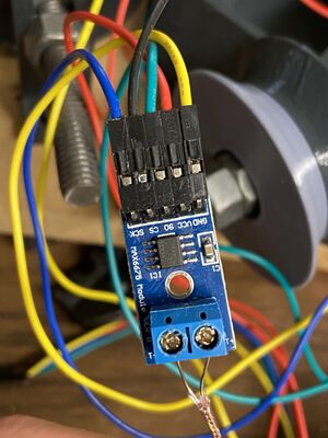
Code below sets up MAX pins
int thermo_so_pin = 50;
int thermo_cs_pin = 53;
int thermo2_cs_pin = 49;
int thermo_sck_pin = 52;

//uses max6675 library to setup sensors
MAX6675 thermocoupleback(thermo_sck_pin, thermo_cs_pin, thermo_so_pin);
MAX6675 thermocouplefront(thermo_sck_pin, thermo2_cs_pin, thermo_so_pin);
THERMOCOUPLES:
To setup the thermocouples, one end of each couple should be connected to the neutral of the power supply, and other end should be connected to one end of the solid state relay. On the same side of the relay as the thermocouple, the other connector should be connected to the live end of the power supply. Then on the other side of the power supply, one of the pins should be connected to 12-35V out on the ramps, and the other to ground on the ramps (positive and negative sides of D9 on the ramps board diagram). This lets the ramps turn on and off the solid state relay, which will in turn stop or start power going to the thermocouple (acting like a switch).
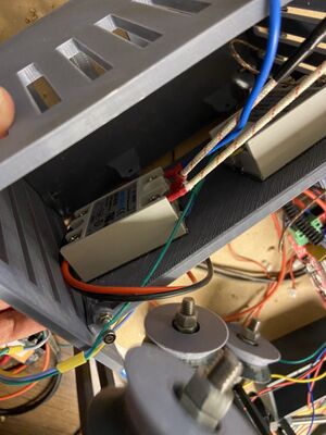

The following code sets up the heater relay:
//set ramps 12v pin
const int HEATER_RELAY_PIN = 9;

//this goes in the setup function
//setup heater pin
pinMode(HEATER_RELAY_PIN, OUTPUT);
digitalWrite(HEATER_RELAY_PIN, LOW);
CURRENT PROJECT STATE:
Here are some images of the current project state at the end of the semester.
3D printed motor mounts and stepper motor:
