|
|
| Line 2: |
Line 2: |
| {{SEARC}} | | {{SEARC}} |
| {{MOST}} | | {{MOST}} |
| | ==Build guide== |
| ==Project Overview== | | ==Project Overview== |
|
| |
|
| Line 231: |
Line 232: |
| </gallery><br /><br /> | | </gallery><br /><br /> |
| ==Build Guide== | | ==Build Guide== |
| Portable Solar Powered 3D Printing System
| |
|
| |
|
| Build Manual
| |
|
| |
| Debbie King
| |
| April 19th, 2013
| |
|
| |
|
| |
|
| |
|
| |
| Abstract
| |
|
| |
| The following is build manual for anyone that would like to build an off-grid portable 3D printing system. The manual contains the bill of materials, tools needed, the step-by-step instructions, as well as links to the repository where all of the necessary files are stored.
| |
| The manual contains as much instruction as possible, so no previous familiarity with 3D printers is needed. All that is needed is a very basic understanding of how DC power works, and basic computer skills. Also the ability to solder and use basic tools is needed.
| |
| Hopefully this document will be helpful. If further assistance is needed please leave your questions on the discussion page of the project homepage http://www.appropedia.org/Mobile_Solar_Powered_3D_Printer_V2.0.
| |
|
| |
| Thank you
| |
|
| |
|
| |
|
| |
|
| |
| Contents
| |
| Abstract 2
| |
| List of Figures 5
| |
| Introduction 6
| |
| Project Overview 6
| |
| Energy source 6
| |
| Energy storage 7
| |
| Energy control circuit 7
| |
| Manufacturing machine 8
| |
| Machine control 8
| |
| Bill of Materials 9
| |
| Tools Needed 12
| |
| Beginning the build 13
| |
| Building the FoldaRap 13
| |
| Installing Software 15
| |
| Preparing the Batteries and Battery Terminal Connectors 21
| |
| Printing the First Parts 27
| |
| Preparing the Combiner Box 33
| |
| Making the Panel Wrap 48
| |
| Finishing the Combiner Box 53
| |
| Using Your New Portable Printer 57
| |
| Appendices 58
| |
| List of Useful Links 58
| |
|
| |
|
| |
|
| |
|
| |
| List of Figures
| |
| Figure 1 - The FoldaRap 8
| |
| Figure 2 - DC only FoldaRap power hookup 15
| |
| Figure 3 - Z-axis frame stabilizing screws 16
| |
| Figure 4 - Aligned batteries 23
| |
| Figure 5 - Bent battery connector pieces 24
| |
| Figure 6 - Quick connect pairs 24
| |
| Figure 7 - Battery terminal wire positioning 24
| |
| Figure 8 - Connector junction 25
| |
| Figure 9 - Complete terminal connector set before heatshrink 26
| |
| Figure 10 - Terminal connectors with heatshrink 27
| |
| Figure 11 - Batteries hooked up 28
| |
| Figure 12 - Insulated quick connects 29
| |
| Figure 13 - Temporary printer power connection 30
| |
| Figure 14 - Front and top view of printer power connection 30
| |
| Figure 15 - Pronterface settings 31
| |
| Figure 16 - Basic Pronterface instructions 32
| |
| Figure 17 - Measuring battery voltage 33
| |
| Figure 18 - Enclosure hole layout 34
| |
| Figure 19 - LED backer used to mark out holes for LEDs 36
| |
| Figure 20 - LED holes on enclosure 37
| |
| Figure 21 - Silicone filling 37
| |
| Figure 22 - Proper wire connector alignment 38
| |
| Figure 23 - Switches connected Building the Charge Controller Circuit 39
| |
| Figure 24 - Charge controller circuit schematic 40
| |
| Figure 25 - Resistor measurement recording 41
| |
| Figure 26 - LED with colour coded insulation 44
| |
| Figure 27 - LEDs with soldered leads 45
| |
| Figure 28 - LEDs in LED backer 45
| |
| Figure 29 - LEDs with heatshrink 46
| |
| Figure 30 - Pushbutton with lead wires 46
| |
| Figure 31 - First parts to get soldered 47
| |
| Figure 32 - Soldering multiple components at once 47
| |
| Figure 33 - Finished top view of charge controller circuit 48
| |
| Figure 34 - Finish board, back view 49
| |
| Figure 35 - Mounted Panel 50
| |
| Figure 36 - Panel wrap layout 51
| |
| Figure 37 - Panel zip ties 52
| |
| Figure 38 - Panels laid out 52
| |
| Figure 39 - Fabric sewing and wire routing guide 53
| |
| Figure 40 - Panels wrapped, wires cut 54
| |
| Figure 41 - Align wires before securing with wire nut 55
| |
| Figure 42 - Negative panel wire secured with panel nut 55
| |
| Figure 43 - LEDs in place 56
| |
| Figure 44 - Completed combiner box 56
| |
| Figure 45 - Battery terminal separator 57
| |
| Figure 46 - System in travel mode 58
| |
|
| |
| Introduction
| |
| The idea of creating a portable means of custom manufacturing for remote areas with little to no electrical infrastructure was conceived by Dr. Joshua M. Pearce. Dr. Pearce, a professor at Michigan Tech University, and an adjunct professor at Queens University, has dedicated much of his research time to finding open-source appropriate technologies (OSAT) for global issues. OSATs are hardware designs that are freely distributed, for anyone to recreate or redesign, that solve a problem for a particular region or culture.
| |
| Dr. Pearce teamed up with the Sustainable Energy Applied Research Centre (SEARC) of St. Lawrence College to design and build the manufacturing system. The main objectives of this project were:
| |
| Design and build a fully portable, custom part manufacturing system.
| |
| Must be completely autonomous, in terms of energy.
| |
| Will run solely on renewable energy.
| |
| Must be open-source and include a full build manual.
| |
| Inexpensive, and easy to reproduce.
| |
| Project Overview
| |
| This section will cover the major components that will make up the system.
| |
|
| |
|
| |
| Energy source
| |
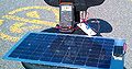
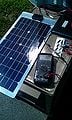
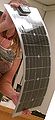
| Photovoltaic energy (PV) was chosen for the energy source. Out of all of the reviewed renewable energy sources, PV is currently the most efficient, portable, and cost effective. While many PV panels on the market have an average area of 18ft2, and can weigh 100lb or more, there are a few companies that make small, lightweight panels, generally meant for boating and camping applications. This system uses five 20W semi-flexible solar panels from a company called Eco-worthy. The panels also boast high efficiency rates, durability, and a very low price tag.
| |
| Energy storage
| |
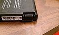
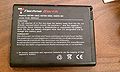
| Lithium-Ion batteries currently have the highest storage density of any battery chemistry that is available for consumer purchase, and falls within the project price range. Li-ions, are cheap, readily available, compact, and come in a variety of different voltages and capacities. This system will use four 14.8V 6600mAH laptop batteries.
| |
| Energy control circuit
| |
| The charge controller is what comprises the majority of the work for this project. It was decided that an off-the-shelf charge controller would not be used. Instead, an open-source custom charge controller would be designed and built.
| |
| The circuit monitors battery levels, prevents overcharging and over-discharging. It also includes over-voltage, and over-current protection to all the components connected to it.
| |
| Manufacturing machine
| |
| The RepRap is an open-source, 3D printer. It works by melting a plastic filament onto a flat printing surface, and building the object upwards, layer by layer. It uses PLA, a biodegradable plastic, and is comprised of up to 70% printable parts, therefor is said to be a self-replicating machine (hence the name RepRap.) The model used in this project is the FoldaRap, shown in Figure 1. The FoldaRap, like all other RepRaps, is open-sourced, but has the unique ability to fold up into a very small footprint, making it ideal for portability, and there for this project.
| |
| Machine control
| |
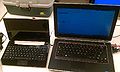
| The last major component included in this system is the computer needed to control the printer. The Efika MX Smartbook was chosen, it is an ultra-portable notebook. Its power runs at an average of 3W, compared to the standard 60W that other notebooks on the market run at. The smartbook can easily last 7 hours on a single charge. Although the smartbook was chosen for this project, it will not be considered a must-buy component in the manual. If the reader already has a laptop with sufficient battery life, it is not required to buy this notebook as well.
| |
|
| |
|
| |
| Bill of Materials
| |
|
| |
| Part Description Website # Unit Price S&H Tax Total Price
| |
| Online purchases
| |
| Printer* FoldaRap - foldable 3D printer http://reprap.org/wiki/FoldaRap_Buyers_Guide
| |
| 1 580.00 70.00 $650.00
| |
| Panels Semi-flexible 20W PV Panels http://www.eco-worthy.com/catalog/product_info.php?products_id=148
| |
| 5 38.00 93.00 $283.00
| |
| Batteries Batteries 6.6Ah 14.8V Li-ion http://www.amazon.com/gp/product/B0026ZRCYE
| |
| 4 33.00 0.00 $132.00
| |
| Fabric** 4 Yards Denier Coated Fabric http://www.onlinefabricstore.net/pack-cloth-fabric/black-420-denier-coated-pack-cloth-fabric-.htm
| |
| 4 6.70 6.95 $33.75
| |
| Suitcase Suitcase 29" http://www.wayfair.com/Travelers-Choice-Amsterdam-29-Expandable-Rolling-Upright-TS6950-UD1160.html
| |
| 1 44.00 0.00 $44.00
| |
| Proto board Single Side 7x9 cm Prototype Circuit Board 720 Holes http://www.ebay.ca/itm/270988465505
| |
| 1 0.99 0.00 $0.99
| |
| Wire 4M Meter Red(2M) Black(2M) 22 AWG http://www.ebay.ca/itm/350745998089
| |
| 1 2.97 0.00 $2.97
| |
| Wire 10M Meter Red(5M) Black(5M) 14 AWG Wire http://www.ebay.ca/itm/370785125610
| |
| 1 23.12 0.00 $23.12
| |
| Laptop*** Ultra Low-power laptop http://www.genesi-tech.com/products/smartbook
| |
| 1 199.00 25.43 $224.43
| |
| *DO NOT purches the 12V Power Supply or female IEC cable With laptop $1,394.26
| |
| **May be purchased at local fabric shop at reduced rate Without laptop $1,169.83
| |
| **Laptop not necessary if one with sufficient battery operating time (>4h) already owned
| |
|
| |
|
| |
|
| |
|
| |
|
| |
|
| |
|
| |
| Circuit Part # Description Digi-Key Part Number Qty Unit Price Shipping/Tax Total Price
| |
| Digi-key Purchases
| |
| Enclosure BOX ABS 10.43X7.28X3.74" GRY 377-1259-ND 1 31.00 8.00 $39.00
| |
| Connectors CONN FAST AWG 14-18 (male) A27924CT-ND 20 0.29 $5.80
| |
| Connectors CONN FAST 14-18 AWG (female) A27623CT-ND 4 0.14 $0.56
| |
| Wire Nut CONN SPLICE TWIST LOCK 14-22AWG WM23949-ND 2 0.11 $0.22
| |
| Wire Nut CONN SPLICE TWIST LOCK 8-22AWG WM23952-ND 1 0.18 $0.18
| |
| Connectors TERM BLOCK PCB 2POS 5.0MM GREEN 277-1667-ND 6 0.38 $2.28
| |
| Tie Wraps WIRE TIE 4.72 18LBS NT RP821-ND 25 0.04 $1.09
| |
| Heatshrink HEATSHRNK POLY 1/4" BLK 4' Q2F014B-ND 1 1.10 $1.10
| |
| Heatshrink HEATSHRNK POLY 3/32" BLK 4' Q2F332B-ND 1 0.57 $0.57
| |
| D1 DIODE GEN PURPOSE 50V 10A R6 10A01CT-ND 1 0.75 $0.75
| |
| D10-13 LED SS 3MM 568NM GRN DIFF 754-1609-ND 3 0.14 $0.42
| |
| D2 DIODE ZENER 10.45V 500MW SOD323F DDZ11ASF-7DICT-ND 1 0.18 $0.18
| |
| D3 DIODE ZENER 11.42V 500MW SOD323F DDZ12ASF-7DICT-ND 1 0.18 $0.18
| |
| D4 DIODE ZENER 12V 500MW DO35 1N5242BFSCT-ND 1 0.13 $0.13
| |
| D5 DIODE ZENER 13.2V 400MW SOD323F D3Z13BF-7DICT-ND 1 0.17 $0.17
| |
| D6 DIODE ZENER 14.72V 500MW SOD323F DDZ15CSF-7DICT-ND 1 0.21 $0.21
| |
| D7-8 LED SS 3MM 625NM RED DIFF 754-1610-ND 2 0.14 $0.28
| |
| D9 LED SS 3MM 588NM YLW DIFF 754-1212-ND 1 0.17 $0.17
| |
| F1-5 FUSE 3A 125V FAST AXL BULK MQ 507-1017-ND 5 0.40 $2.00
| |
| F6 FUSE CERM 250V FAST AXL 3AB 20A F3331-ND 1 2.35 $2.35
| |
| IC1-2 IC VREF SHUNT PREC ADJ TO-92-3 TL431BCLPGOS-ND 2 0.58 $1.16
| |
| IC3 IC DIFF COMPARATOR QUAD 14-DIP 296-9575-5-ND 1 0.80 $0.80
| |
| M1-2 MOSFET N-CH 30V TO220AB 568-7512-5-ND 2 0.81 $1.62
| |
| Circuit Part # Description Digi-Key Part Number Qty Unit Price Shipping/Tax Total Price
| |
|
| |
| R1,13 RES 5.1K OHM 1/4W 5% CARBON FILM CF14JT5K10CT-ND 2 0.09 $0.18
| |
| R10 RES 470 OHM 1/4W 5% CARBON FILM CF14JT470RCT-ND 1 0.09 $0.09
| |
| R14 RES 10 OHM 1/4W 5% CARBON FILM CF14JT10R0CT-ND 1 0.09 $0.09
| |
| R15-16 RES 100 OHM 1/4W 5% CARBON FILM CF14JT100RCT-ND 2 0.09 $0.18
| |
| R17 RES 220 OHM 1/4W 5% CARBON FILM CF14JT220RCT-ND 1 0.09 $0.09
| |
| R2,3,5,6,9,11,18 RES 330 OHM 1/4W 5% CARBON FILM CF14JT330RCT-ND 10 0.06 $0.63
| |
| R4,12 RES 30K OHM 1/4W 5% CARBON FILM CF14JT30K0CT-ND 2 0.09 $0.18
| |
| R7 RES 150 OHM 1/4W 5% CARBON FILM CF14JT150RCT-ND 1 0.09 $0.09
| |
| R8 RES 2.2K OHM 1/4W 5% CARBON FILM CF14JT2K20CT-ND 1 0.09 $0.09
| |
| S1+2 SWITCH ROCKER SPST 20A 250V 1091-1013-ND 2 2.06 $4.12
| |
| S3 SWITCH PUSH SPST-NO 3A 125V EG2025-ND 1 1.36 $1.36
| |
| Digi-Key Total $68.32
| |
|
| |
| Part Dimensions Use Quantity Approx Price
| |
| Local purchases
| |
| Plywood Sheet 16"x20"x1/4" Table top 1 3.00
| |
| Dowels 2' tall x ≤1" diameter Panel supports 3 to 5 2.00
| |
| Total cost without laptop 1,243.15
| |
| Total cost with laptop $1,467.58
| |
|
| |
| Tools Needed
| |
| The following list of tools will cover the entire build. Tools with a letter designation are substitutes for the numbered tool directly before it, for example: 6a) a lighter can be used if a heat gun is not available.
| |
|
| |
| Wire cutters
| |
| Wire strippers
| |
| Knife
| |
| Soldering Iron
| |
| Solder
| |
| Rosin flux
| |
| Heat gun
| |
| Lighter
| |
| Digital multimeter
| |
| 3/64, 1/8, 3/16, 9/32 drill bits
| |
| Cordless drill
| |
| A long skinny screw driver #1 square
| |
| (shaft ≤ 8.5mm in diameter, and ≥ 75mm long)
| |
| Phillips #2 screwdriver
| |
| 1.5mm, 3mm flat screwdriver
| |
| 1.5mm, 2mm, 2.5mm hex keys
| |
| Metal straightedge
| |
| Rotary tool with cutting blade (i.e.: Dremel)
| |
| Box cutter
| |
| Scissors
| |
| Label Maker
| |
| White electrical tape
| |
| Black fine tip permanent marker
| |
| Sewing machine
| |
| Stapler or needle and thread
| |
| Tape measure
| |
| Metal file (round or flat)
| |
| Calculator
| |
| Tweezers (optional)
| |
| Silicone sealant (optional)
| |
|
| |
|
| |
| Beginning the build
| |
| Please go to the project’s main repository https://www.dropbox.com/sh/q4k0khhwcwbkbih/rchdzCo2ck for all of the files needed to complete this project.
| |
| Before the build can begin, the first thing that must be done is part ordering. The purchase links in the Bill of Materials section is only a guide, and was compiled in Canada. Cross referencing part numbers with your local suppliers can result in reduced rates and shipping times.
| |
| Reading through the entire build process before devising a plan of action may also be helpful.
| |
| Building the FoldaRap
| |
| For build instructions on the FoldaRap, please go to: http://reprap.org/wiki/FoldaRap_Build_Manual
| |
| There the FoldaRap’s creator has put together a comprehensive build manual, filled with video tutorials, photos and diagrams.
| |
| Follow the build manual step by step until the Power Supply section is reached. As indicated in the BOM for this project, a 12V power supply is not needed. As the Power Supply section only covers mounting the PSU to the plate, this section can be skipped all together.
| |
| The power wiring is simplified. DC power will be supplied to the front of the male plug socket. . As seen in Figure 2, from the back of the socket it will connect to the switch, then straight to the +/- of the controller board.
| |
|
| |
| Figure 2 - DC only FoldaRap power hookup
| |
| The rest of the FoldaRap build stays the same as in the build manual.
| |
| After the printer is built, there is one more addition that should be made. Glue four t-nuts in place to secure the folding z axis, as seen in Figure 3. Four M4x8 screws can now be quickly screwed in or out for quicker assembly and disassembly. On the prototype, the silicone sealant was used for gluing the nuts in place.
| |
|
| |
| Figure 3 - Z-axis frame stabilizing screws
| |
| Installing Software
| |
| Once the printer is built, there is some software that will need to be installed to run it. All of the information on what is needed to run the printers can be found at http://reprap.org/wiki/Main_Page, but the information is a little scattered, and can be out of date or incomplete. Also, there is a user’s guide to the FoldaRap at http://reprap.org/wiki/FoldaRap_User_Manual#Softwares but it is not geared toward first time 3D printer users. This section will hopefully be a full guide to get the printer printing in the shortest amount of time possible. Taking the time later to get fully acclimated to the printing software will improve your efficiency and print quality. It is strongly encouraged to do more online research to make the most out of the new printer
| |
| Go to https://www.dropbox.com/sh/q4k0khhwcwbkbih/rchdzCo2ck this is the dropbox repository for the project. Any files or documents needed for this build will be found here.
| |
| Open the software folder. Open and install or unpack each file in its numbered order.
| |
| Double click “1 – python-2.7.msi.” Click “download.”
| |
| Preform the setup with the default options. Click “Next” three times, and then “Finish.”
| |
| Python is a programming language commonly used in open source software.
| |
| Double click “2 – printrun-win-Mar2012-slic3r.zip.” Click “download.”
| |
| Unzip to the desired location. It is recommended to set up all of the software directly in the C:/ drive.
| |
| Navigate to the directory the files were extracted to.
| |
| Open the “dist” folder.
| |
| Pronterface, the printer interface software, is now ready to go.
| |
| Go back to the “Software” folder.
| |
| Double click “3 – Foldarap-master.zip.” Click “download.”
| |
| Extract to the desired location.
| |
| Go back to the “Software” folder.
| |
| Double click “4 – slic3r-mswin-x86-0-9-9.zip.” Click “download.”
| |
| Extract to the desired location.
| |
| Navigate to the directory the files were extracted to.
| |
| Open the “Slic3r” folder.
| |
| Slic3r, the software that converts 3D drawing files into the coordinate based printing code, known as Gcode, is now ready to be used.
| |
| Open slic3r
| |
| Click “Cancel” to skip the configuration wizard.
| |
| Click “File > Load Config…”
| |
| Navigate to the “Foldarap-master” folder.
| |
| Open the “Firmware & settings” folder.
| |
| Select “config_slic3r-0093_FoldaRap.ini” and click “Load.”
| |
| Slic3r is now configured with all of the settings specific to the FoldaRap.
| |
| Close Slic3r.
| |
|
| |
|
| |
| Go back to the “Software” folder.
| |
| Double click “5 – Arduino-0023.zip”
| |
| Extract to the desired location.
| |
| Navigate to the directory the files were extracted to.
| |
| Open the “arduino-0023” folder.
| |
| Arduino, the microcontroller programming software is now ready to be used.
| |
| Plug the printer into a USB port of your computer. The printer does not have to be powered for this part, the USB power is sufficient.
| |
| Open Arduino.
| |
| Click “File > Open.”
| |
|
| |
| Navigate to “Foldarap-master > Firmware & settings > Marlin_FoldaRap.” Select any one of the files in this folder, and click “Open.”
| |
| This will open all of the settings for the printer’s firmware.
| |
| If the Efika MX Smartbook is being used, the baud rate must be changed. For most other laptops, skip to step 43.
| |
| Click on the “Configuration.h” tab.
| |
| Scroll down to:
| |
| // This determines the communication speed of the printer
| |
| #define BAUDRATE 250000
| |
| //#define BAUDRATE 115200
| |
| Add “//” infront of the second line, and delete it from the third line, so it reads:
| |
| // This determines the communication speed of the printer
| |
| //#define BAUDRATE 250000
| |
| #define BAUDRATE 115200
| |
| The firmware is now ready to be uploaded.
| |
| Select “Tools > Board” make sure “Sanguino w/ATmega 1284p 16mHz” is selected.
| |
| If the Sanguino option does not appear, restart your computer, and make sure the printer is plugged in before opening Arduino.
| |
| Click the upload button, wait until “Finished uploading” is displayed. The printer firmware is now installed.
| |
| Preparing the Batteries and Battery Terminal Connectors
| |
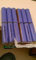
| Stack the batteries on top of one another, and secure with tape as in Figure 4.
| |
| Cut 6 x 3" pieces of 14 gauge wire, 3 red and 3 black.
| |
| Cut 2 x 30” pieces of 14 gauge wire, 1 red and 1 black.
| |
| Strip 1/4" off each end of all of the 3” wires. On the 30” wires strip ¼” off one end, and ½” off of the other.
| |
|
| |
| Figure 4 - Aligned batteries
| |
| Bend the 3” pieces into a U shape, see Figure 5.
| |
|
| |
| Figure 5 - Bent battery connector pieces
| |
| Double up the male quick connects over one another in 8 pairs as in Figure 6.
| |
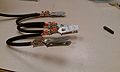
| Secure one pair to one end of a 3" wire piece with the crimpers or pliers. Figure 7 shows a connector pair about to be crimped to a wire.
| |
|
| |
| Figure 6 - Quick connect pairs
| |
|
| |
| Figure 7 - Battery terminal wire positioning
| |
| Line up another 3" piece of the same colour beside the bare end of the first wire. Use another connector pair to secure those two wires together, like in Figure 8.
| |
|
| |
| Figure 8 - Connector junction
| |
| Repeat step 10 with another 3" wire, then again with the 30" piece of the same colour, try to keep the connector pairs vertically aligned with each other, so they will fit into the batteries easily.
| |
| Now you should have one side of the connectors finished, it should look like Figure 9.
| |
|
| |
| Figure 9 - Complete terminal connector set before heatshrink
| |
| Repeat steps 9-12 with the other colour to make the remaining connector.
| |
| Cut 8 x 1” pieces of the large heatshrink.
| |
| Slip one piece over each connector pair. Line up the heatshrink to leave ¼” of the tabs visible. The finished product should look like Figure 10.
| |
| When the batteries are ready to be hooked up, the black set will go on the left, the red on the right. Figure 11 shows what the batteries will look like hooked up, except red wires were not used for the prototypes positive connectors. The batteries positive and negative terminals are laid out like:
| |
|
| |
|
| |
| Figure 10 - Terminal connectors with heatshrink
| |
|
| |
| Figure 11 - Batteries hooked up
| |
| Printing the First Parts
| |
| Now that the printer is built, and a power source is ready, the first print can be made. The printer is built to run off 12 to 30VDC, so the batteries 14.8V batteries are ideal for running the printer.
| |
| As the batteries are shipped approximately 75% charged, the batteries in the prototype arrived 79% charged, they have approximately 19.8Ah of energy in them to start. Testing on this system has determined and average of energy draw of 5.92Ah per hour of printing (although it has been found that the energy draw varies greatly with print time. Short prints take more energy/time since the majority of the energy is used in the initial heating, comparatively little during printing.) There for there is approximately 3h 15m of printing time in the batteries when they arrive. The first the printed parts take 1h 20m to print, still leaving lots of charge on the batteries.
| |
| Cut 2 x 8’ lengths of wire, 1 red, 1 black.
| |
| Strip the wires ¼” on one side, ½” on the other
| |
| Use two of the leftover insulated female quick connects from the FoldaRap kit. Attach one to the ¼” stripped end of each of the wires. Aside from one wire being red rather than white, you should end up with Figure 12.
| |
|
| |
| Figure 12 - Insulated quick connects
| |
|
| |
| Connect the wires to the ends of the battery connectors with the blue wire nuts, as in Figure 13.
| |
|
| |
| Figure 13 - Temporary printer power connection
| |
| Making sure the power switch on the FoldaRap is in the “Off” position, connect the quick connects to the appropriate polarity power tab on the printer. Figure 14Figure 14 shows how it will look.
| |
|
| |
| Figure 14 - Front and top view of printer power connection
| |
| Now connect the battery connectors to the battery as previously shown in Figure 11, using extreme care not to short out the battery terminals since the battery terminal separator has not been printed yet.
| |
| Download “First Print.gcode” from “STL” folder in the dropbox repository.
| |
| Connect the printer to the computer.
| |
| Open Pronterface.
| |
| Refer to Figure 16 for a basic explanation of how to use Pronterface.
| |
| Click “Settings > Options.”
| |
| Copy the settings in Figure 15.
| |
| Load “First Print.gcode.”
| |
| Power on the computer via the big blue switch.
| |
| Connect to the printer through Pronterface.
| |
| The port and desired baud rate must be selected.
| |
| If the port window is empty, click the drop down arrow, and select “COMX” X will be a number of whatever port the printer is connected to, as Pronterface automatically searches for the printer on all of the ports.
| |
| Select the baud rate you set the firmware to, either 250000 or 115200. Press “Connect”
| |
|
| |
| Figure 16 - Basic Pronterface instructions
| |
| Check to make sure all of the motors are moving in the proper directions, and level the bed. Instructions on setting up the printer can be found at http://reprap.org/wiki/FoldaRap_User_Manual
| |
| Set the heat to 200, and the bed to 55. Once the temperatures are reached press “Print”
| |
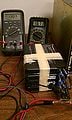
| Monitor the battery voltage during the print. Stop the print if the batteries near 12V, although that should not happen. Figure 17 shows the easiest spot to measure the battery voltage.
| |
| You should now have the first three printed parts needed to finish this build.
| |
|
| |
|
| |
| Figure 17 - Measuring battery voltage
| |
| Turn off the printer power, and disconnect it from the computer.
| |
| Twist the wire nuts off that are connecting the printer and batteries.
| |
| Gently straighten the wire ends out by hand. Cut ¼” off of all the ends so only ¼” of bare wire is remaining.
| |
| Preparing the Combiner Box
| |
| Next, holes must be made in the side of the ABS enclosure that will be facing outward.
| |
| The holes do not have to be laid out in any set order, Figure 18 is the layout of the prototype. There must be:
| |
|
| |
| 2 – 27.3x12.3mm holes for the switches
| |
| 14 – 3/16” holes, 2 for printer, 2 for batteries, 10 for panels
| |
| 2 – 3/16” holes for fastening in LED backer
| |
| 7 – 1/8” holes for LEDs
| |
| 1 – 9/32” hole for push button
| |
| To line up the LED holes properly, the “led back.stl” will be used.
| |
| Drill two 3/16” holes, 46mm apart from each other.
| |
| Using two M3x12 screws, fasten the LED back part to the outside of the enclosure, with the small holes flush against the enclosure like in Figure 19.
| |
|
| |
| Figure 19 - LED backer used to mark out holes for LEDs
| |
| Using a small drill bit, marker or pen, make a mark on the enclosure through each of the holes.
| |
| Drill a 1/8” hole in the center of each of the pairs of marks. The holes should turn out as in Figure 20, except the top two holes will be the same size as the five bottom holes.
| |
|
| |
| Figure 20 - LED holes on enclosure
| |
| To make the rectangular holes for the rocker switches a Dremel type rotary cutting tool is preferable. If a Dremel is not available, a box cutter can be used, but use extreme caution to avoid injuries. Using a metal straightedge along the cutting lines will help to make neat precise cuts.
| |
| If there cut marks outside of the intended perimeter, fill them in with the silicone sealant as in Figure 21.
| |
|
| |
| Figure 21 - Silicone filling
| |
| Once the holes are cut, snap the rocker switches into place.
| |
| Label one switch for the panels, and one for the batteries.
| |
| Thread the ends of the two battery connectors into the enclosure.
| |
| Crimp or tightly secure with pliers, one of the female quick connects to the red lead of the battery connectors.
| |
| For the most secure connection, align the wire in the connector so the bottom tabs wrap around the wire insulation, and the top tabs tighten around the bare wire as shown in Figure 22. Securing the tabs around the insulation first will help prevent slipping during tightening.
| |
|
| |
| Figure 22 - Proper wire connector alignment
| |
| Cut 3 x 3” pieces of red 14 gauge wire. Strip ¼” of insulation off each end.
| |
| Put a female quick connect on one end of each of the wires.
| |
| Connect all four of the quick connects to the back of the switches, see Figure 23.
| |
|
| |
| Figure 23 - Switches connected Building the Charge Controller Circuit
| |
| The charge controller circuitry in this design is where the component connections and protection circuitry take place. The circuit was designed with maximum simplicity, and minimal cost in mind. Almost all of components are through hole as opposed to SMT to facilitate ease of build. Please refer to Figure 24 for the wiring diagram.
| |
| Unpack all of the electrical components from the supplier, verify all of the proper parts were sent.
| |
| Leave the four SMT zener diodes in their labled packages, and set them to the side.
| |
| Measure all of the 330Ω resistors, as each one is measured, write it on a piece of paper and place that resistor on top.
| |
|
| |
| Figure 25 - Resistor measurement recording
| |
| Measure the 470, 150 and 2.2kΩ resistors, R10, R7, and R8 respectively. Record their values.
| |
|
| |
|
| |
|
| |
| Figure 24 - Charge controller circuit schematic
| |
|
| |
| Use the measured value of R10 in Equation 1
| |
| 〖R10〗_meas/1.4148=〖R11〗_calc
| |
| Equation 1
| |
| Of the measured 330Ω resistors, choose one with the closest value to R11calc.
| |
| As a double check, enter the measured values of R10 and the chosen R11 into Equation 2:
| |
| [R10/R11+1]2.495=1/2 of desired Min Battery Voltage
| |
| Equation 2
| |
| The resulting value should be very close to 6.025. Never use a combination that gives a value of less than 6.01, as that would let the battery drain to a critically low level.
| |
| Using the measures values of R7 and R8, calculate:
| |
| 〖[1/R7+1/R8]〗^(-1)=R_tot
| |
| Equation 3
| |
| The calculated Rtot should be approximately 140.
| |
| Use Rtot from Equation 3 in Equation 4
| |
| R_tot*2.3567=〖R6〗_calc
| |
| Equation 4
| |
| Choose the closest match between R6calc and the remaining measured 330Ω resistors. As a double check, enter the measured values of R7, R8, and the chosen R6 in the formula:
| |
| [[R6[1/R7+1/R8]+1]2.495=1/2 of desired Max Battery Voltage
| |
| Equation 5
| |
| The resulting value should be very close to 8.375. Never use a combination that gives a value of more than 8.395, as that would allow the battery to become close to over charged.
| |
| Out of the remaining eight 330Ω resistors, chose two that are almost identical in value. These will be R2 and R3. R2 and R3 should ideally be within 0.1Ω of eachother.
| |
| Precise values for R5, R9, and R18 are unnecessary, any of the remaining 330Ω resistors will do.
| |
| Get a rough idea of how you would like to set up the circuit board, particularly where the zener diodes will be going.
| |
| When working the four SMT zener diodes, only take one out of its package at a time to avoid getting them mixed up.
| |
| Place a zener on the board (using tweezers if possible) so each lead is touching a different pad.
| |
| Clean the tip of the soldering iron very well. Apply a small bead of solder to the tip of the iron. Touch the iron to the pad just long enough for the solder to flow onto the pad and over the lead of the diode.
| |
| Repeat this for the other lead, then the other 3 SMT zeners.
| |
| If the line that denotes the cathode on the body of the zener is to small or faint to see, use the diode setting on the multimeter. Touch one lead to each side of the diode. If the meter reads ≈0.7V then the end that the positive lead of the meter is on is the anode. If the meter reads OL then it is the cathode.
| |
| Cut 16 x 6” pieces of 22 gauge wire, 8 red and 8 black.
| |
| Strip ¼” off of each end. Save the cut off pieces of insulation, and as in Figure 26 slide one red and one black piece onto the leads of the LEDs. The longer lead of the LEDs is the anode, so place the red insulation on the long lead.
| |
|
| |
| Figure 26 - LED with colour coded insulation
| |
| Now the leads can be trimmed and the polarities will still be known. Trim the leads so ¼” is left past the insulation.
| |
| Solder a 6” piece of wire to the end of each lead, see Figure 27.
| |
|
| |
| Figure 27 - LEDs with soldered leads
| |
| Slide the LED lead wires into the LED backer. Figure 28 shows the direction the LEDs should be put in the backer.
| |
|
| |
| Figure 28 - LEDs in LED backer
| |
| Cover the solder joints in heatshrink. Do not touch the backer while heating the heatshrink. Leave to cool completely before touching the printed part to avoid bending the part. The finished product should look like Figure 29.
| |
|
| |
| Figure 29 - LEDs with heatshrink
| |
|
| |
| Solder the two remaining 6” wires to the pushbutton. Cover the solder joints in heatshrink. Figure 30 shows blue leads, although yours will have one black and one red.
| |
|
| |
| Figure 30 - Pushbutton with lead wires
| |
| Steps 25 - 27 are sugesstions as to how to assemble the circuit board. Any assembly method that resuslts in a circuit matching Figure 24, is acceptable.
| |
| Continue to populate the board by placing the components with the lowest profiles on first, this is the resistors, and the last zener, as in Figure 31.
| |
|
| |
| Figure 31 - First parts to get soldered
| |
| Fold up a towel or other large soft fabric until it is at least an inch thick. Place it on top of the components in the board. Secure the fabric to the board, using string, a belt, ect. Figure 32 shows an example of this method. Now the board can be flipped over, and multiple components can be soldered at once, while staying flush against the board.
| |
|
| |
|
| |
| Figure 32 - Soldering multiple components at once
| |
| Repeat the process with increasing component heights, until everything is on the board. Finished product should look similar to Figure 33. The photos used in this manual are of the prototype. Some improvements were made to the current BOM to either reduce cost or size, so there may be some differences in the photos. The zener diodes were mounted on small pieces of vero board to make circuit testing easier. Also, the fuses in the current BOM are through hole fuses, to save space and cost.
| |
|
| |
| Figure 33 - Finished top view of charge controller circuit
| |
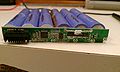
| Flip the board over, and make the necessary connections with the wire. The 22 gauge wire can be used for everything except for the connections between the batteries, panels, and printer. This will include the wires that conect to the drains and sources of M1 and M2. The back of the finished board should look something like .
| |
|
| |
|
| |
| Figure 34 - Finish board, back view
| |
| Be sure to connect all of the unused pins of the LM2901 to ground.
| |
| Making the Panel Wrap
| |
| Start by drilling a pair of holes in each corner of each panel with the 3/16th drill bit. The holes in the pair should be approximately ¼” apart. See Figure 35. Be sure to drill far away from the actual PV cells, and keep the blue protective tape on while drilling, to avoid getting scratches on the panel surface.
| |
| Clear a large work area on the floor.
| |
| Lay the fabric flat out, it should be 12’ x 5’. Fold it over once, so it is 6’ x 5’.
| |
| The way the panels are laid out will depend on what side the suitcase opens on. See Figure 36.
| |
|
| |
|
| |
| Figure 35 - Mounted Panel
| |
|
| |
|
| |
| Figure 36 - Panel wrap layout
| |
| The panels are just under 1” thick where the junction boxes are, so leaving 1 ¼” between the first two panels, and adding an extra 1 ¼” between each panel after, leaves enough room for the panel to be comfortably rolled around each other.
| |
| So as in the top example of Figure 36, where the suitcase opens to the left, the panels will start at the bottom right corner of the fabric. The next panel will be placed 1 ¼” to the left of the first. The third will be placed 2 ½” to the left of the second. The fourth 3 ¾” left of the third. The last panel will be 5” left of the fourth. If your suitcase opens to the right, the opposite will be true.
| |
| Using scissors cut a small slit in the upper layer of fabric under each drilled hole in the panels.
| |
| Thread a zip tie through the holes in the panel, and through the upper layer of the fabric to secure the panel to the fabric. See Figure 37.
| |
|
| |
| Figure 37 - Panel zip ties
| |
| You should now have something like Figure 38.
| |
| Sew or staple the fabric where indicated in Figure 39 by the green lines.
| |
| Cut slits in the top layer of fabric centered above each panel large enough for the wires to be fed through. The slits are indicated by the blue Xs in Figure 39.
| |
|
| |
| Figure 38 - Panels laid out
| |
|
| |
| Figure 39 - Fabric sewing and wire routing guide
| |
| Feed the wires through the slits in the direction of the larger gaps between panels as indicated in Figure 39.
| |
| Take three of the thin sheets of padding that the panels came packed in and place them in the pockets of the upper half of the fabric. Place one in the middle pocket, and the other two in the outside pockets. Three are used, to provide a bit of cushioning without too much bulk.
| |
| Sew or staple the top edge shut.
| |
| You can now fold the top half of fabric down over the panels and roll them up.
| |
| Bundle the wires together with tie wraps to keep them neat and in line.
| |
| Cut all of the wires the same length as the shortest pair.
| |
| Strip the ends of positive wires ¼”, and the negative wires ½”. The panel wrap should resemble Figure 40.
| |
|
| |
| Figure 40 - Panels wrapped, wires cut
| |
| Finishing the Combiner Box
| |
| At this point all of the holes should be made in the enclosure, and only the two battery wires are threaded through, plus the wires that are attached to the back of the switches.
| |
| Thread the panel wires into the enclosure.
| |
| Cut 1 x 3” black 14 gauge wire. Strip it ½” at one end, and ¼” at the other.
| |
| Line up the ½” end up with the negative wires of the panels as in Figure 41.
| |
|
| |
| Figure 41 - Align wires before securing with wire nut
| |
| Secure the 6 wires together with the red wire nut, see Figure 42.
| |
|
| |
| Figure 42 - Negative panel wire secured with panel nut
| |
| Fit the LEDs into the LED holes, and secure the LED backer with two m3x8 screws as in Figure 43.
| |
|
| |
| Figure 43 - LEDs in place
| |
| Secure the push button in its hole with the nut provided.
| |
| Screw the remaining wires in their respective terminals.
| |
| Upon completion the inside of the combiner box should resemble Figure 44.
| |
|
| |
| Figure 44 - Completed combiner box
| |
| Finishing the System
| |
| Snap the printed battery terminal separator into place. See Figure 45. The terminal separator will prevent any shorts between the battery terminals if a connector slips out.
| |
|
| |
| Figure 45 - Battery terminal separator
| |
| Mount the enclosure on the upper inside wall of the suitcase, on the wall opposite from where the door attaches.
| |
| Screw the lid of the enclosure on.
| |
| Print the “Table legs.stl” from the STL folder in the repository.
| |
| Screw the table legs onto the plywood sheet. The plywood now can sit level on top of the suitcase for a portable tabletop.
| |
| Now to pack it up.
| |
| Place the panel wrap in the case with the junction boxes and wires at the top. Secure with the upper set of suitcase straps.
| |
| Place the batteries on their side, underneath the combiner box.
| |
| Place the folded FoldaRap in front of the panels, secure with the bottom suitcase straps.
| |
| Figure 46 is what the finished product should look like.
| |
|
| |
|
| |
| Figure 46 - System in travel mode
| |
| Using Your New Portable Printer
| |
| You can now travel wherever you’d like with your new portable custom manufacturing system. Feel free to share and/or modify this design as you see fit. If any issues arise during the build, please contact us through the discussion page of the project homepage http://www.appropedia.org/Mobile_Solar_Powered_3D_Printer_V2.0.
| |
| Enjoy.
| |
|
| |
|
| == See Also == | | == See Also == |