This is an implementation of using a photoelectric smoke detector to trigger the reset pin on the Beaglebone Black Rev C being used on the MOST Athena Delta 3D Printer. The purpose of this design is to prevent and minimize printer damage, overheating, temperature runoff, and fire risk when a 3D printer is running unattended.
Smoke Alarm Mod in place
Materials & Tools Needed
Photoelectric Smoke Alarm of any kind, such as the one here (not the model pictured in this tutorial) -- SCAD models made for one with a 12" mounting disk, but can be modified for other types
Print off 3 Arms and one Base Fixture; set models to a scale of 10 in your slicer.
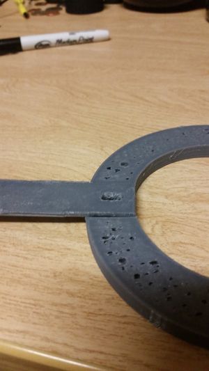
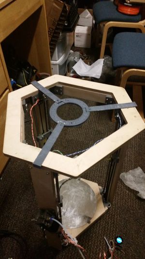
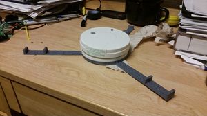
Fig.1: Close up of fixture and joint connected Use M3 bolts to mount arms to fixture in the insets of the fixture, shown in Figure 1. use nuts to hold in place. (superglue can be used as substitute for arm-fixture joining). Test to ensure frame fits your printer, shown in figure 2. Fig.2:View of mod frame from top
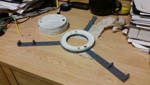
Fig.3:Mount with BracketUse M3 bolts to connect the mounting bracket of smoke alarm to printed fixture, shown in Figure 3. Use nuts to fasten.
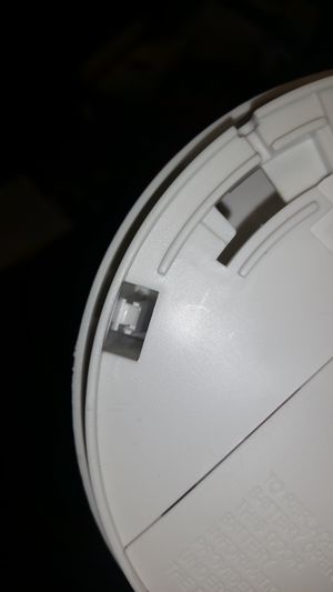
Fig.4:Pins to be opened to access electronics of smoke detectorOpen smoke alarm with screwdriver via loosening 3 pins along the bottom of the alarm, shown in Figure 4. Open case when pins are loosened
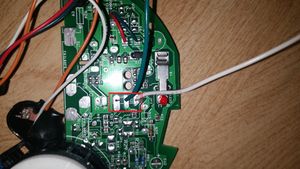
Fig.5:Smoke Alarm electronics with Sound output pins highlightedUse Soldering Iron to remove speaker wires, and solder in 18 Gauge wire as shown in Figure 5.
Place 9 Volt Battery into smoke alarm.
Fig.6:Mount with DetectorPlace Smoke alarm onto mounting bracket, shown in Figure 6.
Place assembly onto printer frame.
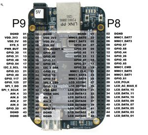
Fig.7:Beaglebone Pinout, from Element14Connect Wire soldered onto the 'B' terminal (white wire in Figure 4) to ground pin 43, shown in Figure 7. Connect Other wire (Shown green in Figure 4) to Pin 10, 'SYS_RESET_N'. Remove Bridge bracket to place wire, then reinsert bridge bracket on top of wire.
Notes, Known issues and possible fixes
current Design causes the fire alarm to constantly trigger reset of the Beaglebone when smoke is detected, preventing the Beaglebone from turning on until the fire alarm is reset.
Future Improvements
A future improvement is to set the output of the smoke alarm to a data pin on the beaglebone, scripted to stop Firmware (i.e. Franklin) and send an email / notification to the printer owner, then shutting off the entire system.