
To Catch the Sun/525W solar van
This page is the start of a description of a 525 W solar power system containing both AC and DC loads in a Ford Transit van named Dusty and made by Tressie George.
-
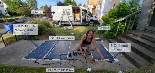 3 175W flexible monocrystalline photovoltaic panels connected in parallel.
 -
 Aerial View of Solar System on Dusty.
 -
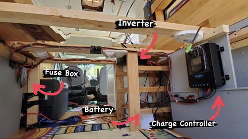 System set up with charge controller, inverter, battery storage, and fuse box.
 -
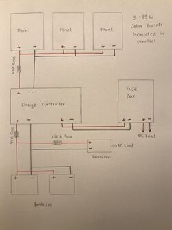 Sketch of solar van system including main components.


Parts
[edit | edit source]Below are the list of parts, supplies, and tools you will need. Depending on sourcing, you will likely be buying slightly different components.
-
![175W 12V Flexible Monocrystalline Solar Panel[1]](/w/images/thumb/c/cf/175W_12V_Flexible_Monocrystalline_Solar_Panel.png/250px-175W_12V_Flexible_Monocrystalline_Solar_Panel.png) 175W 12V Flexible Monocrystalline Solar Panel[1]
175W 12V Flexible Monocrystalline Solar Panel[1] -
![12V 125Ah Battery[2]](/w/images/thumb/2/25/%212V_125Ah_Battery.png/250px-%212V_125Ah_Battery.png) 12V 125Ah Battery[2]
12V 125Ah Battery[2] -
![40 Amp 12V/24V DC Input Solar Charge Controller[3]](/w/images/thumb/a/a9/40_Amp_12V-24V_DC_Input_Solar_Charge_Controller.png/250px-40_Amp_12V-24V_DC_Input_Solar_Charge_Controller.png) 40 Amp 12V/24V DC Input Solar Charge Controller[3]
40 Amp 12V/24V DC Input Solar Charge Controller[3] -
![Inverter[4]](/w/images/thumb/b/b3/100_W_Inverter.png/250px-100_W_Inverter.png) Inverter[4]
Inverter[4] -
![12 Circuit Fuse Block[5]](/w/images/thumb/7/7e/12_Circuit_Fuse_Block.png/250px-12_Circuit_Fuse_Block.png) 12 Circuit Fuse Block[5]
12 Circuit Fuse Block[5] -
![DC 12V LED Lights[6]](/w/images/thumb/2/2e/DC_12V_LED_lights.png/250px-DC_12V_LED_lights.png) DC 12V LED Lights[6]
DC 12V LED Lights[6] -
![Cable Entry Housing[7]](/w/images/thumb/8/8c/Cable_Entry_Housing.png/330px-Cable_Entry_Housing.png) Cable Entry Housing[7]
Cable Entry Housing[7] -
![Male and Female Branch Connectors[8]](/w/images/thumb/8/8b/Solar_Male_and_Female_Branch_Connectors.png/250px-Solar_Male_and_Female_Branch_Connectors.png) Male and Female Branch Connectors[8]
Male and Female Branch Connectors[8] -
![10ft. 10 AWG Connector Adapter Cables[9]](/w/images/thumb/9/97/10ft._10_AWG_Connector_Adaptor_Cables.png/250px-10ft._10_AWG_Connector_Adaptor_Cables.png) 10ft. 10 AWG Connector Adapter Cables[9]
10ft. 10 AWG Connector Adapter Cables[9] -
![8ft. 10 AWG Connector Cabes[10]](/w/images/thumb/2/2b/8ft._10_AWG_Connector_Cables.png/250px-8ft._10_AWG_Connector_Cables.png) 8ft. 10 AWG Connector Cabes[10]
8ft. 10 AWG Connector Cabes[10]
![175W 12V Flexible Monocrystalline Solar Panel[1]](/File:175W_12V_Flexible_Monocrystalline_Solar_Panel.png)
![12V 125Ah Battery[2]](/File:!2V_125Ah_Battery.png)
![40 Amp 12V/24V DC Input Solar Charge Controller[3]](/File:40_Amp_12V-24V_DC_Input_Solar_Charge_Controller.png)
![Inverter[4]](/File:100_W_Inverter.png)
![12 Circuit Fuse Block[5]](/File:12_Circuit_Fuse_Block.png)
![DC 12V LED Lights[6]](/File:DC_12V_LED_lights.png)
![Cable Entry Housing[7]](/File:Cable_Entry_Housing.png)
![Male and Female Branch Connectors[8]](/File:Solar_Male_and_Female_Branch_Connectors.png)
![10ft. 10 AWG Connector Adapter Cables[9]](/File:10ft._10_AWG_Connector_Adaptor_Cables.png)
![8ft. 10 AWG Connector Cabes[10]](/File:8ft._10_AWG_Connector_Cables.png)
Assembly Instructions
[edit | edit source]The following section contains step-by-step instructions on how to assemble this 535 W photovoltaic system.

Use the panel adaptor cables and connectors to connect the 3 solar panels. Start by joining the adaptor cables to the positive and negative terminals on each panel. Then use the connectors to attach the three panels in parallel. To do this, use the connectors to join all the negatively charged wires. Then do the same thing but with all of the positively charged wires. Each wire carrying a negative charge should only be connected to other wires that are also negatively charged. Similarly, each wire carrying a positive charge should only be connected to other wires that are also positively charged.

Once all the positively charged wires are joined to one wire, connect this wire with a 40A fuse to prevent power surges to the system. Next, connect a red wire coming out of the same 40A fuse, this will attach to the charge controller in a later step.

Warning: Do not let the positive and negative terminals of the batteries touch each other. Using the red wire, attach that to the positive terminal of the battery. Use that same wire and connect it to the positive terminal of the second battery. Repeat this same process for the black wire, except attach it to the negative battery terminals.

Connect a red wire to the battery terminal, then connect that same wire to a 150A fuse. Next connect another red wire to the opposite side of the same fuse, this will attach to the inverter in a later step. Then, connect a black wire to the negative terminal of the battery, this will attach to the inverter in a later step.

Connect another red wire to the positive battery terminal, this same wire will connect to a 40A fuse. Next, connect another red wire to the opposite side of the same fuse, this will connect to the charge controller in a later step. Then, connect a black wire to the negative terminal of the battery, this same wire will connect to the charge controller in a later step.

Connect the positively charged red wires to one side of the fuse box, in a later step those same wires will be connected to the charge controller. Then, connect the negatively charged black wires to the fuse box above the red wires that were just installed. Those same black wires will be connected to the charge controller in a later step. Repeat this process for the other side of the fuse box, except those wires will be connected to the loads.

Using a red wire, connect the positive terminal of the inverter to the 150A fuse from step 4. Then, connect the black wire from step 4 into the negative terminal of the inverter.

Install the red and black wires from the battery in step 5 to the charge controller battery terminals. This is done by unscrewing the terminals, inserting the black wire into the negative terminal labeled Bat- and the red wire into the positive terminal labeled Bat+, and closing and securing both terminals with the screwdriver.

Install the red and black wires from step 6 to the charge controller load terminals. Unscrew the terminals and insert the red wire into the Load+ terminal and the black wire into the Load- terminal. Close and secure both terminals with the screwdriver.

Install the red an black wires from steps 1 and 2 to the charge controller PV terminals. Unscrew the terminals and insert the red wire into the PV+ terminal and the black wire into the PV- terminal. Close and secure both terminals with the screwdriver.

Safety and Disclaimer
[edit | edit source]This guide is provided as a free reference. Electricity is dangerous. Batteries have stored energy and can be very dangerous if you short them (i.e., connect the positive and negative terminal with something conductive like metal). You can even hurt yourself with a screwdriver if you try hard enough. Please proceed at your own risk. Appropedia (and any authors) shall not be held responsible for any damages as a result of any activities contained within this guide.
Notes
[edit | edit source]- ↑ https://www.amazon.com/Vmaxtanks-Vmaxslr125-rechargeable-Solar-Inverters/dp/B00ACNO2AO/ref=sr_1_1?crid=2BYWWIL5YHHLZ&keywords=vmax+tanks+12v+battery+125ah+SLA+rechargeable+deep+cycle+battery+for+use+with+pv+solar+panels&qid=1669504655&sprefix=vmax+tanks+12v+battery+125ah+sla+rechargeable+deep+cycle+battery+for+use+with+pv+solar+panel%2Caps%2C137&sr=8-1&ufe=app_do%3Aamzn1.fos.08f69ac3-fd3d-4b88-bca2-8997e41410bb
- ↑ https://www.amazon.com/Vmaxtanks-Vmaxslr125-rechargeable-Solar-Inverters/dp/B00ACNO2AO/ref=sr_1_1?crid=2BYWWIL5YHHLZ&keywords=vmax+tanks+12v+battery+125ah+SLA+rechargeable+deep+cycle+battery+for+use+with+pv+solar+panels&qid=1669504655&sprefix=vmax+tanks+12v+battery+125ah+sla+rechargeable+deep+cycle+battery+for+use+with+pv+solar+panel%2Caps%2C137&sr=8-1&ufe=app_do%3Aamzn1.fos.08f69ac3-fd3d-4b88-bca2-8997e41410bb
- ↑ https://www.homedepot.com/p/Renogy-8-ft-10-AWG-Charge-Controller-and-Battery-Connector-Tray-Cables-RNG-TRAYCB-8FT-10/310330268
- ↑ https://www.homedepot.com/p/Renogy-8-ft-10-AWG-Charge-Controller-and-Battery-Connector-Tray-Cables-RNG-TRAYCB-8FT-10/310330268
- ↑ https://www.homedepot.com/p/Renogy-8-ft-10-AWG-Charge-Controller-and-Battery-Connector-Tray-Cables-RNG-TRAYCB-8FT-10/310330268
- ↑ https://www.homedepot.com/p/Renogy-8-ft-10-AWG-Charge-Controller-and-Battery-Connector-Tray-Cables-RNG-TRAYCB-8FT-10/310330268
- ↑ https://www.homedepot.com/p/Renogy-8-ft-10-AWG-Charge-Controller-and-Battery-Connector-Tray-Cables-RNG-TRAYCB-8FT-10/310330268
- ↑ https://www.homedepot.com/p/Renogy-8-ft-10-AWG-Charge-Controller-and-Battery-Connector-Tray-Cables-RNG-TRAYCB-8FT-10/310330268
- ↑ https://www.homedepot.com/p/Renogy-8-ft-10-AWG-Charge-Controller-and-Battery-Connector-Tray-Cables-RNG-TRAYCB-8FT-10/310330268
- ↑ https://www.homedepot.com/p/Renogy-8-ft-10-AWG-Charge-Controller-and-Battery-Connector-Tray-Cables-RNG-TRAYCB-8FT-10/310330268
Authors
[edit | edit source]- Lonny Grafman
- Joshua Pearce
| Authors | Lonny Grafman, Joshua M. Pearce |
|---|---|
| License | CC-BY-SA-4.0 |
| Organizations | To Catch the Sun/525W solar van |
| Cite as | Lonny Grafman, Joshua M. Pearce (2022–2024). "To Catch the Sun/525W solar van". Appropedia. Retrieved July 11, 2026. |