
"Implemented" is not in the list (Idea, Designed, Modelled, Prototyped, Verified, Deployed, Commercialized, Clinical trial, In progress) of allowed values for the "Status" property.
The basis for this project was a component of a semester long team project at Michigan Tech to design, develop, and test a robot of our own imagination. Our team decided on creating a grilled cheese making robot, and as part of that a circuit board to control the robot was necessary.
The electrical design for the board was simple in concept-- create a board capable of controlling 3 separate stepper motors and a resistive heating device, while taking in human input, mechanical positions, and thermal readings (to allow for closed-loop control). This could be accomplished (and was accomplished) quite easily using a microcontroller with pulse width modulation capabilities and a few breakout boards for stepper motor control.
Design
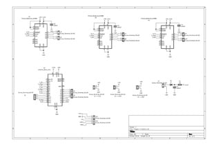
Pictured above is the finished schematic for Mr. Flipper's control board, broken down into pieces that descriptively single out design requirements. The general design was as such-- and Arduino Nano for the microcontroller, as they are robust enough and easy to replace. Connected to PWM pins on the Arduino Nano, there are 3 breakout Pololu A4988 stepper motor driver boards, which are themselves wired to power and some screw terminals for later connection to motors. Additionally connected to the Nano via PWM pins is a 3x1 screw terminal set intended to be the connection points for the resistive heating device. In order to ensure closed-loop control, several connection points were made to be later utilized as potentiometer based position sensors for the stepper motors. A power supply circuit is included for basic safety and distribution. Finally, there is a set of five screw terminals connected to "Clk, Latch, Data, +5V, GND." This port is intended to be a connection point for an NES controller. Human control was a specification for the design, and NES controllers are rather simplistic, so an NES controller was chosen as the control input for convenience and novelty.

The final routed PCB for Mr.Flipper's control board is pictured above. It should be noted that this board was explicitly made to be single layer for ease of creation/acquisition-- any pictured top layer traces in practice were replaced with a wire connection. Having a single layer board was technically not a required design specification, but it was chosen so as to quickly manufacture the board at home as opposed to contracting it out.
Materials and Costs
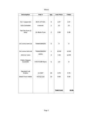
The bill of materials for just this board (and the class project at large) costed approximately $63 dollars, but taking into account only the parts utilized on the board, the cost drops down to approximately $15.30. The entire robot required further expenses (i.e the mechanical components and auxiliary parts out of the scope of the electrical team). The completed BOM is listed below.
In total, this project took approximately a collective 20-25 hours to complete, from first concepts to soldering.
Final Project Results

Pictured above is the completed result of the team's efforts-- an automatic grilled cheese making robot. The complete circuit board can be seen rested on the bottom of the device. The 3 stepper motors collectively control the XY positioning of the spatula, and the rotation of the spatula. The device can pick up an unfinished grilled cheese, lift it up into the resistive heating device (seen mounted near the top of the device), leave the sandwich until cooked perfectly, and then remove the sandwich from the device and present it to be eaten.