
Control Board for Grilled Cheese Maker/fr

La base de ce projet était une composante d'un projet d'équipe d'un semestre à Michigan Tech visant à concevoir, développer et tester un robot de notre propre imagination. Notre équipe a décidé de créer un robot de fabrication de fromage grillé, et dans ce cadre, un circuit imprimé pour contrôler le robot était nécessaire.
La conception électrique de la carte était simple : créer une carte capable de contrôler 3 moteurs pas à pas séparés et un dispositif de chauffage résistif, tout en prenant en compte l'entrée humaine, les positions mécaniques et les lectures thermiques (pour permettre un contrôle en boucle fermée). Cela pourrait être accompli (et a été accompli) assez facilement en utilisant un microcontrôleur doté de capacités de modulation de largeur d'impulsion et quelques cartes de dérivation pour le contrôle du moteur pas à pas.
Conception
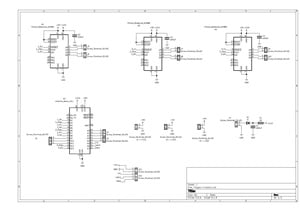
L'image ci-dessus montre le schéma final du tableau de commande de M. Flipper, décomposé en éléments qui distinguent de manière descriptive les exigences de conception. La conception générale était la suivante : Arduino Nano pour le microcontrôleur, car ils sont suffisamment robustes et faciles à remplacer. Connectées aux broches PWM de l'Arduino Nano, il y a 3 cartes de commande de moteur pas à pas Pololu A4988, elles-mêmes câblées à l'alimentation et à certaines bornes à vis pour une connexion ultérieure aux moteurs. Un jeu de bornes à vis 3x1 destiné à servir de points de connexion pour le dispositif de chauffage résistif est également connecté au Nano via des broches PWM. Afin d'assurer un contrôle en boucle fermée, plusieurs points de connexion ont été réalisés pour être ensuite utilisés comme capteurs de position basés sur un potentiomètre pour les moteurs pas à pas. Un circuit d'alimentation est inclus pour la sécurité et la distribution de base. Enfin, il y a un ensemble de cinq bornes à vis connectées à « Clk, Latch, Data, +5V, GND ». Ce port est destiné à être un point de connexion pour une manette NES. Le contrôle humain était une spécification pour la conception, et les contrôleurs NES sont plutôt simplistes, c'est pourquoi un contrôleur NES a été choisi comme entrée de contrôle pour des raisons de commodité et de nouveauté.

Le PCB final routé pour le tableau de commande de Mr.Flipper est illustré ci-dessus. Il convient de noter que cette carte a été explicitement conçue pour être monocouche pour faciliter la création/acquisition : dans la pratique, toutes les traces de la couche supérieure illustrées ont été remplacées par une connexion filaire. Techniquement, le fait d'avoir un panneau monocouche n'était pas une spécification de conception requise, mais il a été choisi de manière à pouvoir fabriquer rapidement le panneau à la maison plutôt que de le sous-traiter.
Matériaux et coûts
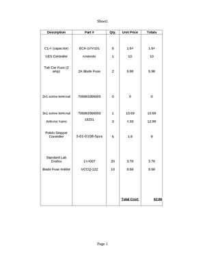
La nomenclature de cette carte (et du projet de classe dans son ensemble) a coûté environ 63 dollars, mais en prenant uniquement en compte les pièces utilisées sur la carte, le coût tombe à environ 15,30 dollars. L'ensemble du robot a nécessité des dépenses supplémentaires (c'est-à-dire les composants mécaniques et les pièces auxiliaires hors de portée de l'équipe électrique). La nomenclature complétée est répertoriée ci-dessous.
Au total, ce projet a pris environ 20 à 25 heures collectives, depuis les premiers concepts jusqu'à la soudure.
Résultats finaux du projet

La photo ci-dessus représente le résultat complet des efforts de l'équipe : un robot automatique de fabrication de fromage grillé. Le circuit imprimé complet peut être vu posé au bas de l’appareil. Les 3 moteurs pas à pas contrôlent collectivement le positionnement XY de la spatule, et la rotation de la spatule. L'appareil peut ramasser un fromage grillé inachevé, le soulever dans le dispositif de chauffage résistif (vu monté près du haut de l'appareil), laisser le sandwich jusqu'à ce qu'il soit parfaitement cuit, puis retirer le sandwich de l'appareil et le présenter pour être mangé. .