
Solar Tracking System Using Arduino
| Type | |
|---|---|
| Authors | |
| Status | |
| Years |
Abstract
[edit | edit source]This page describes how to design and built a solar tracking system using Arduino. Usage of solar systems are increasing rapidly and the technology is advancing day by day. The sunlight only lasts during the day and we need to get the maximum usage of sun during the day.
Project goals
[edit | edit source]Efficiency of a solar panel is typically around 20%. Although there panels that have high efficiency than 20% they are not for commercial use as their costs are relatively high. So we have to look for a another method to increase the efficiency of the solar system.
To get the maximum efficiency from a solar panel it should be directed towards the sun at all times. But a fixed solar panel can not achieve this. So the sun tracking concept came forward. Simply put, instead of a fixed solar panel, the panel is constructed to be moved around one of its axis to face the sun at all times during the day.
- Main object of this design more accurate tilting device to increase the efficiency of the solar panel.
- Second object is to create a sun tracker which is lower in the price than the existing tracking devices.
Working Principle
[edit | edit source]The solar panel has PV cells. These PV cells detect the light intensity and according to that power is generated. The tracker adjusts the direction which the solar panel facing to get the maximum light intensity.
2 LDRs are fixed to the edges of the solar panel. LDRs produce low resistance when light falls on them. The servo motor connected to the panel, rotates the panel along its axis in the direction of Sun.Panel is to rotate in a way that light intensity on two Light Dependent Resistors are compared and panel is rotated towards LDR which have high intensity(low resistance) compared to other LDR.Once the difference between the two LDR's resistance goes beyond the pre set value, the servo motor will rotate towards the sun to make that difference go below the pre set value, and thus the panel faces directly towards sun as the sun changes position during the day. This way the tracker adjusts the panel perpendicular to the sunlight because of that less light is reflected. Hence, it absorbs more energy from the sunlight which can be converted into power.
Design
[edit | edit source]Required Components
[edit | edit source]- Servo Motor (sg90)
- Solar panel
- Arduino Uno
- LDR’s X 2 (Light Dependent Resistor)
- 10K resistors X 2
- 9V Battery
- Wires
The circuit diagram for the solar tracking Arduino project is shown below. It is a very simple & easy to build circuit.
-
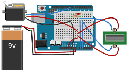 Wiring Diagram
Arduino is powered by the 9V battery. Connection of the wires are as above diagram.
Testing
[edit | edit source]The main performance metric is the accuracy of the device, in terms of positioning the solar panel axis to the user input target angle. To measure this we tested user input angles and the measured the actual angle which the motor turned.
| Target Angle (Degrees) | Measured Angle (Degrees) |
|---|---|
| 10 | 9.8 |
| 20 | 20.1 |
| 30 | 29.9 |
| 40 | 39.8 |
| 50 | 50.2 |
| 60 | 59.5 |
| 70 | 69.6 |
| 80 | 79.5 |
| 90 | 89.7 |
According to the measurements, practical accuracy is around + or - 0.5 degrees. The metal frame physically blocks the motors from moving past 90 degrees. So the device is technically capable of positioning from -90 to 90 degrees,
Next steps
[edit | edit source]The accuracy of the implemented prototype can be increased from using a geared stepper motor. The step angle can be reduced by gearing down the stepper motor, allowing for adjustments of small fractions of a degree. The gearing can also reduce the vibration of the panel. Another option would be to implement a dual axis tracker using the same principle applied here and adding another x axis along with the already implemented y axis with so that the panel can also rotate along the x axis.
Conclusions
[edit | edit source]The implemented device mostly fulfilled the main goals of the project. The original size prototype could not be implemented and only the smaller prototype model was created. Regarding the main specifications accuracy, movement range, and accepting user inputs from an external device were accomplished. The model offers accuracy within +/- 0.5 degrees, which according to standards, accurate enough for solar panel trackers. Although improvements can be added, device has the potential as a method for controlling solar panel trackers at low speeds and high precision.
References
[edit | edit source][1] R. Ford and C. Coulston, Design for Electrical and Computer Engineers, McGraw-Hill, 2007, p. 37
[2] Shin, H. (2019). Altitude and azimuth angle concurrent driving type solar tracking apparatus. 10,404,207.
[3] Judkins, Z. (2019). Photovoltaic assembly for use in diffuse weather conditions and related methods. 10,415,974.
[4] Sumathi, Vijayan, et al. “Solar Tracking Methods to Maximize PV System Output – A Review of the Methods Adopted in Recent Decade.” Renewable and Sustainable Energy Reviews, vol. 74, pp. 130–138, July 2017.
[5] Yao, Yingxue, et al. “A Multipurpose Dual-Axis Solar Tracker with Two Tracking Strategies.” Renewable Energy, vol. 72, pp. 88–98, Dec. 2014.
Contact details
[edit | edit source]Eng. Ridma Kaveendra
ridmakaveendra7@gmail.com
| Authors | |
|---|---|
| License | CC-BY-SA-4.0 |
| Cite as | Ridma Kaveendra (2021–2023). "Solar Tracking System Using Arduino". Appropedia. Retrieved July 10, 2026. |