Ingénieurs Assistance Internationale -
Ingénieurs sans Frontières
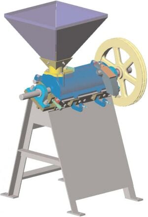
Construction manual of a rice husker Equipment designed and manufactured in Haiti by the workshops-schools of Camp Perrin
Developed in cooperation with Codéart and the workshops-schools of Camp Perrin
Philippe Carlier (†) Cédric Vanhoolandt Project engineer ISF Construction manual of a rice husker[1] Equipment designed and manufactured in Haiti by the workshops-schools of Camp Perrin
Collection "Technical manuals" Manual created by ISF with support of the General Directorate for Cooperation and Development (DGCD)
Ingénieurs Assistance Internationale - Ingénieurs sans Frontières 2003 http://www.isf-iai.be mail@isf-iai.be Avenue du Marly, 48, 1120 Brussels - Belgium
We thank all the people without whom this manual could have not seen the light of day, and in particular: the members of the workshops-schools of Camp Perrin, Roger Loozen (Codéart) and Michel Taquet (GRET).
Technical sheet Production schedule: 250kg/h for a recommended motorization of 15CV (~ 11kW) Training: only the manual Use: business use; for small or medium communities Maintenance: lubrication of bearings, regular maintenance of engine, replacement of worn parts: drums and knives Features: low cost manufacturing, simple manufacturing techniques, robust
Introduction[edit | edit source]
This guide is intended for all workshops wishing to put in place the manufacturing of a rice husker, adapted to the constraints of non-industrialised countries.
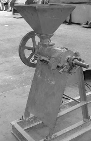
The rice husker described in this manual is based on a model that has proved its worth for many years; notably the Engelberg rice husker (see Annex 5). The huller is successfully produced in Haiti since 1994 by the workshops-schools of Camp Perrin (AECP). These two elements assure the huller of being well adapted to the constraints of most countries, where the technical expertise is limited, both in regards to the manufacturing as the use. Also, numerous arguments plead in favor of local production:
- In case of machine failure or wear, spare parts can be easily found and are thus available in a timely manner;
- Manufacturing of the huller provides handwork for the locals;
- A transfer of pre-industrialised techniques is done
- Production costs for the machine are lower, which permits the wider distribution of a machine that is beneficial to the community;
- A pre-industrial technology transfer takes place, marking the first step for a shift towards serial production
This model of huller has many parts made in a foundry. Unfortunately, many workshops do not posses this technology. In this case, the best solution is to locally outsource these parts. If this solution also not possible, all these parts can be ordered from the Belgian A.S.B.L. Codéart 2. A version of this machine made solely from mechanical welded parts is currently being researched. We warn the reader about the apparent simplicity of the huller: its manufacturing demands hefty experience and mechanical know-how.
The manual includes not only the detailed drawings of all parts of the huller, but also those of all the special tools used for their manufacturing: templates for piercing, foundry molds,... The tools described in this manual are those also used at Camp Perrin, but may be adapted depending on the tools or other materials available in your workshop.
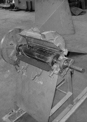
The huller described here is a horizontal axis model. It is equipped with an engine (diesel or electric) with a performance of about 250kg/h for a motorization of around 15CV, thus about 11kW.
The product obtained by the rice farmer is not inmediately usable for human consumption:it is the "paddy" rice or "Dressed" rice. The grain of the rice, or "caryopsis", to be eatible, must be removed from its envelopes that cover it (see diagram in Annex 4). Through this operation, we obtain "husked rice" or "brown rice" when it is complete, as well as a byproduct.
1 Workshops-schools of Camp Perrin - BP 183 Les Cayes - Haiti info@aecp-haiti.org 2 Codéart ASBL - Chevémont, 15 - Homburg 4852 - Belgium Tel: +32 / 87 78 59 59 - Fax: +32 / 87 78 79 17 www. codeart.org - info@codeart.org
When the we dehusk the rice, we first remove the hard envelopes. Then we take on the thinner ones. Through this process, the rice slowly changes color, and when it is complete, it is brown. When completely shelled, the rice is white. Commercially, husked rice is called "cargo rice".
The rice husker performs the shelling of (separation of glumes and bracts) and laundering or elaboration (separation of the different layers of pericarp) in a single operation. It is therefore not possible to separate the two by-products, namely the chaff (glumes and bracts) and the bran (pericarp). As a result, despite the high nutritional value of the bran (rich in vitamins B and E and other nutritional elements; see the table of nutrient values in Annex 4), the by-products can not be used to enrich the soil or to mulch the treenurseries. Indeed, the chaff is unfit for animal consumption because it may cause irritations and bleedings in the intestines.
To avoid loss of important nutrients, it is possible to steam the rice. From a technical perspective, drying is a precooking process of the pre-hydrated paddy rice with a water content of around 30%. Steaming improves the technical quality of the rice (cost-effectiveness of shelling) by resolving the cleaved grains, thus reducing the margin of broken rice. It causes some yellowing of the grain as the heat treatment is more or less pronounced. It also increases the nutritional qualities by enriching the kernel with B-vitamins and minerals that were initially concentrated in the pericarp 3. Milled, parboiled rice also has a higher vitamin content than raw milled rice.
At the exit of the huller, the rice is only partially bleached. It could be allowed to pass through a second time in the machine to get a grain which is a bit whiter. This operation is however not recommended because the more time the grain spends in the machine, the more is wasted from the rice, and a larger amount of nutritional value is lost. Some more complex machines separate glumes and bracts before entry into the polishing drum where the bran is separated from the grain. A machine which allows this separation of the chaff and the bran is currently being researched by Codéart. A prototype is already being tested. This machine can easily be mounted on the huller described in this manual. The function of the huller is then limited to separating the bran of the grain after which the chaff is separated in a next step.
3 J.F. Cruz and Souare D., 1997.
Principle of operation[edit | edit source]
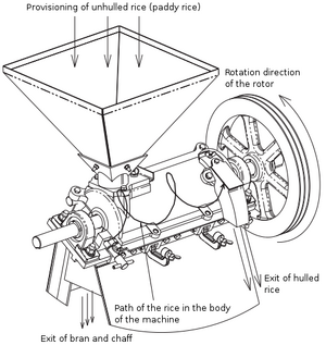
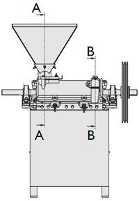
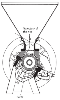
When the huller runs, we introduce rice into the hopper. The part of the rotor which is located below the hopper acts as an Archimedes screw, and "pushes" the rice to the other end of the rotor. Once some of the rice has passed into the body of the huller, it is driven by the horizontal stries of the central part of the rotor into a rotational movement.
When the grains of the non-husked rice arrives at the knife, the space it has to move along (between the rotor and the knife) is heavily reduced. The knife opposes the rotation of grains. The chaff and the bran surrounding it then "rub" along the edge of the knife and the elevations of the rotor, leading to their separation of the grain by necking and scouring. This allows the husking of the rice. The level of scouring is set by the opening of the exit for the husked rice: the more it is closed, the more the rice is forced to stay longer in the device, which accentuates the shelling. The pieces in which the bran and the chaff are cut, are small enough to pass through the sieve.
While revolving around the rotor, the rice also advances towards the exit, driven by the rice still located in the feed hopper. Once it arrives at the exit, it can escape through an opening with a especially for this purpose created form. The position of the release is placed relatively high, which allows the last separation between the rice and the chaff which has not yet been evacuated by the sieve. The grains of the rice, because of its weight, is projected onto the exit by inertia. The lighter chaff remains in the body of the huller and continues to turn until exits through the sieve. This separation allows to not require the winnowing (separation of dust and remaining waste) of the rice produced by this huller.
The manufacturing of the huller[edit | edit source]
Bill of materials[edit | edit source]
Manufactured parts[edit | edit source]
Qty. Number Name Material Standard 2 00-001 hinge steel St 37 2 01-001 angle back foot steel St 37 1 01-002 angle forward left foot steel St 37 1 01-003 angle front right foot steel St 37 2 01-004 reinforcement sheet steel St 37 2 01-005 flat steel body support steel St 37 4 01-006 flat steel ground fixation steel St 37 1 01-006 angle left spar steel St 37 1 01-008 angle right spar steel St 37 1 01-009 front sheet steel St 37 1 01-010 rear sheet steel St 37 2 01-011 crossed angle steel St 37 1 02-001 lower body cast iron FGL 250 2 02-002 closing clamp cast iron FGL 250 1 02-003 hulling knife Ac with spring 5ISi7 2 02-004 knife support cast iron FGL 250 2 02-005 adjustment screw for knife steel Ck45 3 02-006 sieve clamping support cast iron FGL 250 3 02-007 sieve support cast iron FGL 250 2 02-009 sieve maintenance barette steel 1 03-001 axis diameter 2*h7 steel Ck45h7 1 03-002 primary hulling cylinder white iron 1 03-003 secondary hulling cylinder white iron 1 03-004 drive pulley cast iron FGL 250 1 03-005 nut primary cylinder cast iron FGL 250 1 03-006 nut secondary cylinder FGL 250 1 03-008 end key DIN 6885-A 12x8x120 steel 1 03-009 central key DIN6885-A 12x8x56 steel Ck 45 1 04-001 supply hopper steel St 37 1 04-002 upper body cast iron FGL 250 1 04-003 feeding mouth cast iron FGL 250 1 04-004 exit mouth cast iron FGL 250 1 04-005 steel exit control sheet St 37 1 04-006 closure exit sheet steel St 37 1 04-007 closure supply sheet steel St 37 4 joint-axis body felt
Note: See the table of standards of metals in Annex 3.
Standard Parts[edit | edit source]
Qty. Designation Material Standard 8 washers M6 steel DIN 125 A 4 washers M8 steel DIN 125 A 15 washers M10 steel DIN 125 A 6 washers M16 steel DIN 125 A 4 ankle diam.10 x 80 DIN 1480 springed Ac 1 eared screw M8 x 16 DIN 316 Ac 8.8 GT 1 eared screw M10 x 20 DIN 316 Ac 8.8 GT 2 eared screws M10 x 40 DIN 316 Ac 8.8 GT 4 screws hexagonal M8 x 30 Ac 8.8 DIN 933 1 hexagonal screws M8 x 16 Ac 8.8 DIN 933 1 hexagonal screws M10 x 25 Ac 8.8 DIN 933 12 hexagonal screws M10 x 30 Ac 8.8 DIN 933 3 hexagonal screws M10 x 40 Ac 8.8 DIN 933 2 hexagonal screws M10 x 60 Ac 8.8 DIN 933 3 hexagonal screws M12 x 50 Ac 8.8 DIN 934 6 hexagonal screws M16 x 70 Ac 8.8 DIN 933 8 hexagonal nut M6 Ac 4.6 DIN 934 4 hexagonal nut M8 Ac 4.6 DIN 934 M16 hexagonal nut 6 Ac 4.6 DIN 934 8 screws with hollow head M6 x 40 Ac A 8.8 DIN 963 2 kit clamping manchon 2 bearings with protected housing 2 sieves steel 2 joint leather
See section 3.7 for further information regarding the 4 last pieces above.
We note that the two lists above (paragraphs 3.1.1 and 3.1.2) oly include the construction parts of the huller. They thus not include neither the tools nor the manufacturing parts.
In addition, the workshop that wishes to produce this model of huller must have at least the following material:
- A lathe;
- A milling machine or joiner's bench;
- A sheet cutter;
- A welding post;
- A drill.
Identification of the different sets[edit | edit source]
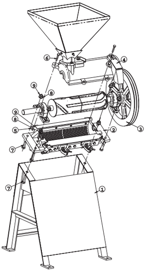
Rep. Qty. Number Name Material Standard 1 1 01-000 assembly support 2 1 02-000 assembly of lower body 3 1 03-000 assembly rotor 4 1 04-000 assembly upper body 5 2 00-001 hinge steel St 37 6 2 hexagonal screws M10 x 60 Ac 8.8 DIN 933 7 6 hexagonal screws M16 x 70 Ac 8.8 DIN 933 8 6 washers M16 steel DIN 125 A 9 6 hexagonal nuts M16 steel DIN 934 Note: See the tables with standards of the metals in Annex 3.
The huller can be broken down into four sub-assemblies (respectively the support, the lower body, the rotor and the upper body) where each can be separatly mounted and then later assembled to one another. We describe the four sub-assemblies in the following paragraphs in detail.
Support[edit | edit source]
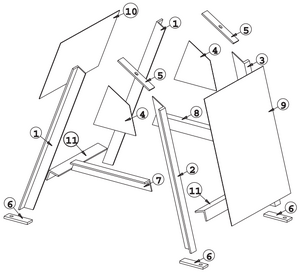
Rep. Qty. Number Name Material Standard 1 2 01-001 rear foot angle steel St 37 2 1 01-002 left front foot angle steel St 37 3 1 01-003 right front foot angle steel St 37 4 2 01-004 reinforcement sheet steel St 37 5 2 01-005 flat plate body support steel St 37 6 4 01-006 flat fixation plate ground steel St 37 7 1 01-006 left spar angle steel St 37 8 1 01-008 right spar angle steel St 37 9 1 01-009 front sheet steel St 37 10 1 01-010 rear sheet steel St 37 11 2 01-011 crossed angle steel St 37
Note: See the table of standards for the metals in Appendix 3.
The support serves to assure the maintenance of the huller at a height which is acceptable to the user and to fix the machine to the ground to avoid all awkward movements. The support, manufactured by AECP, is created only mechanically welded. Its creation poses no particular problem to any welder with a minimum of experience.
We note however that the support was a piece made in a foundry with most older models manufactured in series. The workshops that have a foundry could perhaps be interested in using this method... The two drilled holes in the upper part (upper fixation body) must be made after welding the assembly together to ensure correct tolerance of the distance.
The assembly plans and details of the support and its constructional components are found in Appendix 1, drawings 01-000 et seq.
The lower body[edit | edit source]
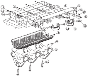
Rep. Qty. Number Name Material Standard 1 1 02-001 lower body cast iron FGL 250 2 2 02-002 closure clamp cast iron FGL 250 3 1 02-003 huller knife springed Ac 51Si7 4 2 02-004 knife support cast iron FGL 250 5 2 02-005 adjustment screw for knife steel Ck45 6 3 02-006 sieve clamping support cast iron FGL 250 7 3 02-007 sieve support cast iron FGL 250 8 2 02-008 sieve steel 9 2 02-009 maintenance bar of sieve steel 10 2 joint-axis body felt 11 3 hexagonal screws M12 x 50 Ac 8.8 DIN 934 12 2 eared screws M10 x 40 DIN 316 Ac 8.8 GT 13 4 ankles dia. 10x80 DIN 1480 springed Ac 14 8 screw with bored head M6 x 40 Ac A 8.8 DIN 963 15 8 washers M6 Ac DIN 125 A 16 8 hexagonal nuts M6 Ac 4.6 DIN 934 17 12 washers M10 Ac 4.6 DIN 125 A 18 12 hexagonal screws M10 x 30 Ac 8.8 DIN 933
Note: See the table of the standards of the metals in Appendix 3.
The "lower body" assembly serves to support the rotor. It also has the function of ensuring the fixation of the sieve, allowing the separation of the grain and mixing chaff and bran.
The drawings of the assembly and the mounting of the assembly of the lower body are found in Appendix 1, drawings 02-000.
The lower body[edit | edit source]
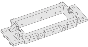
(Rep.1, see Appendix 1, drawing 02-001). This part is the basis of the huller as most other pieces are connect to it. It is molded in cast iron and has no particular mechanical features. The raw part must undergo several modifications: a milling of the upper surface to ensure a certain tightness with the upper body. Several holes are then made on drilling templates. The detailed drawings of these templates can be found in Appendix 2, drawings A1-000 and A2-000.
The clamp closure[edit | edit source]
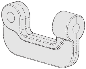
(Rep.2, see Appendix 1, drawing 02-002) This piece should be created in cast iron or in a material with a comparable or inferior durability: the clamp is actually designed to break in case of inoparability or abrupt blocking of the machine, thus avoiding damage to the essential parts of the huller. The drilling of the two holes are done by means of a template.
The knife of the huller[edit | edit source]
(Rep.3, see Appendix 1, drawing 02-003) This piece, in combination with the hulling cylinders, allow the separating of the chaffs and brans of the rice. The knife of the huller must be replaced regularly, because it comes in in contact with the chaff of rice which is very abrasive. To limit the wear nevertheless, the knife is made in steel à ressorts with increased durability (see characteristics in Appendix 3). For this reason, we must be very careful during the milling, as advancing too quickly can cause the tools to break.
The knife support[edit | edit source]
(Rep.4, see Appendix 1, drawing 02-004) This part provides the link between the knife and adjustment screw. One could imagine of removing this part by putting the knife directly in contact with the adjustment screw. But the knife support provides an important feature: like the clamp closure, it is a rupture part. In the event of a severe impact in the mechanism, the support brakes, which permits the release of the knife, and avoids in most cases to breaking of parts that are more difficult or expensive to replace. This part is therefore made in cast iron or a material which is comparable or inferior in durability.
The adjustment screw for the knife[edit | edit source]
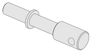
(Rep.5, see Appendix 1, drawing 02-005) At both ends of the knife is a screw to allow the adjustment of the distance between the knife and the hulling cylinders (this distance should be slightly higher than the diameter of hulled rice, but lower than that of the paddy rice). We must try to keep the knife parallel to the rotor axis, so that it works evenly over its entire length.
The tightening of the sieve support[edit | edit source]
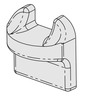
(Rep.6, see Appendix 1, drawing 02-006) This part holds the thightening screw that allows the tightening of the sieve.
It is molded in cast iron and has no particular mechanical features. On the contrary, in case of excessive stress, it must break as well in order to protect other parts. The raw part is drilled on a template, after which the holes are tapped.
The sieve support[edit | edit source]
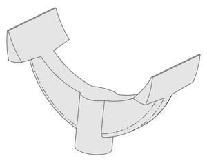
(Rep.7, see Appendix 1, drawing 02-007) The sieve support has as function to secure the sieve, and to stick it against the maintenance bars which assure its fixation to the other side. Its curvature also allows the sieve to retain its cylindrical shape.
It is molded in cast iron and has no particular mechanical features.
The sieve[edit | edit source]
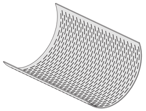
(Rep.8, see Appendix 1, Plan 02-008) The screen is a grid whose holes are big enough to allow the chaff and bran to cross, but also small enough to not allow the hulled rice to cross the grid.
It is strongly advised to subcontract this piece. Its manufacturing is not overly difficult, but requires too much time for insufficiently equipped workshops. A supplier is proposed (see page 24). Beginning with a flat piece, we still need to give it an adequate radius of curvature.
The maintenance bar for the sieve[edit | edit source]
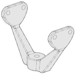
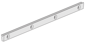
(Rep.9, see Appendix 1, drawing 02-009) The maintenance bar has a notch in which the bord of the sieve fits into. The sieve support holds the sieve in this notch so that it can not escape.
This piece should be made of hardened steel as it is subjected to strong wear through scouring.
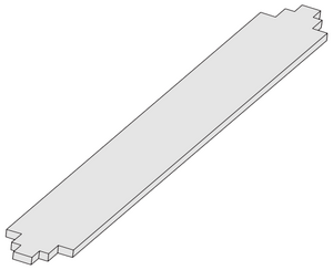
The two main sides of this piece are milled on an angle of 5 degrees. In order to have have sufficient precision with this angle, the piece is milled on a template. When the first side is milled, we turn the piece and mill the other side. The detailed drawing of this template can be found in Appendix 2, drawing A4-000.
The rotor[edit | edit source]
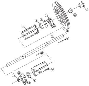
Rep.Qty.Nr. Designation Material Standard 1 1 03-001 axis Ø 2" h7 steel Ck45h7 2 1 03-002 primary hulling cylinder white cast iron 3 1 03-003 secondary hulling cylinder white cast iron 4 1 03-004 pulley drivetrain cast iron FGL 250 5 1 03-005 nut primary cylinder cast iron FGL 250 6 1 03-006 nut secondary cylinder cast iron FGL 250 7 1 hexagonal screws M10 x 40 Ac 8.8 DIN 934 8 2 03-007 seal (waterproof leather washer) leather 9 1 03-008 end key DIN 6885-A 12x8x120 steel Ck45 10 1 03-009 central key DIN6885-A 12x8x56 steel Ck45 11 2 bearing en fonte a semelle 12 2 kit thightening manchon
Note: See the table of standards of the metals in Appendix 3.
The axis[edit | edit source]
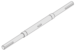
(Rep.1, see Appendix 1, drawing 03-001) The axis ensures the maintenance of the various moving parts in the huller. It also ensures the pulley transmission to the working parts. We create it by turning a round sheet 2. Three junctions of cotters are then milled.
The primary hulling cylinder[edit | edit source]
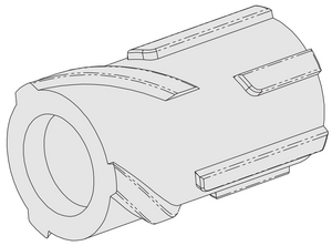
(Rep.2, see Appendix 1, drawing 03-002) This cylinder has two functional parts:
- the part that lies below the hopper has oblique elevations which act like a neverending screw that guide the paddy rice to the exit;
- the part that lies at the center of the body has parallel elevations on the axis that perform the same function as the knife. One could almost say they are "rotating knives."
This piece must be very durable. It must have a strong resistance against wear and scouring. The non-hulled rice is indeed very abrasive and cylinders wear fairly quickly. As such, it is molded in white cast iron, ie to obtain a significant hardness from the creation of a piece cooled in ordinary cast iron (which is gray cast iron, see the standards in Appendix 3), we must ensure a rapid cooling of the cast iron in the mold. Therefore, it we cool it, not in a sand mold but in a steel mold or by casting. We then talk of cooling in a metal shell, which requires a bit of little specific know-how. The rapid cooling of molten iron acts acts as a quenching. The hardness of the finished piece is about 30 HRC (or 96kg/mm ²). The difficulty with this method lies with the creation of the of the shells. For this part, the molds were created through a regular cast (white cast iron, see the standards in Appendix 3). We had to cut the the mold in 3 sections of 120 degrees and modify the outer side to allow their insertion in the sand model. Codéart can help you for the realisation of this piece, or even give you one.
A junction of cotters must then be modified in the cylinder profile of the hulling cylinder. As this piece has a great hardiness, we must keep in mind that it is very difficult to modify. Be careful to not break the tools!
The secondary hulling cylinder[edit | edit source]
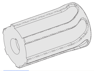
(Rep.3, see Appendix 1, drawing 03-003) This cylinder has two functional parts such as the primary cylinder:
- the part which is located opposite the to the exit and designed to facilitate the exiting of the rice;
- the part that lies in the center of the body also includes elevations parallel to the axis that act as a knife and ensure the hulling.
This part is also molded in white cast iron and must have a great durability, in order to resist wear, see the pragraph above.
One could ask himself the question why the two cylinders have not been assembled into a single cylinder. Firstly, because a single cylinder would be much more difficult to cast. Also, the prmary cylinder wears much faster than secondary one. Savings are thus possible on these parts by not replacing more than one part at a time. Nevertheless, the AECP in collaboration with Codéart, are momentarily carrying out the testing of a version with a single cylinder, cast in fused iron (white cast iron and chromium, see characteristics in Appendix 3), which would allow the avoiding of the two drawbacks cited above.
The pulley drivetrain[edit | edit source]
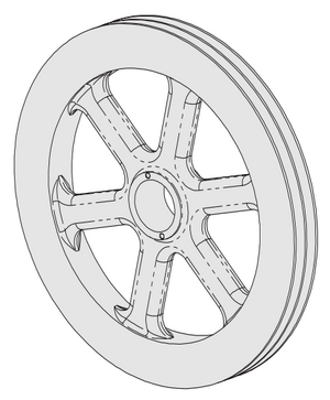
(Rep.4, see Appendix 1, drawing 03-004) It is through the pulley that the belt transmits power to the engine of the axis. The mass and inertia of the pulley are deliberately hightened: when the engine used is a single cylinder diesel engine, the non-negligable inertia of the pulley allows to control a movement that would otherwise be subject to abrupt movements. The pulley is mounted on the axis by means of a conical manchet.
This piece is molded in cast iron and has no partcular mechanical features. The central hole is conical and must be created on a lathe. The two gorges of belts are equally turned.
The attaching of the pulley[edit | edit source]
The attachment of the pulley is done by cylindrical mounting and adjusted clamping, or more precisily, the mounting is done by means of a tightening screw, oblique put, to secure the key (see Figure 25 and drawing 03-004).The oblique placing of the screw is imposed by the configuration of the pulley which not allows to drill a hole perpendicular to the axis (this should be corrected in a later version of the pulley and its foundry mold). Although this solution may seem rudimentary, it is nevertheless quite satisfactory. Moreover, it eliminates the need to place an extra part, or a attachment platform, a conical clamp, or part that is difficult to make or find locally.
The nuts of the primary and secondary dehusking cylinders[edit | edit source]
(Rep.5 & 6, see Appendix 1, drawings 03-005 & 03-006) These two pieces are identical, except for the net, which is left for the nut of the primary cylinder and right for the secondary cylinder.
These parts are cast in cast iron and have no particular mechanical characteristics.
The bearings[edit | edit source]
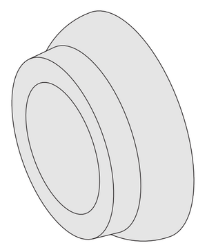
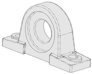
The bearings are standard tightening bearings by conical clamp. The bearings used by AECP are bearings of the NTN brand type UKP-209, but other brands also supply bearings similar in all respects; an example are the SKF type SY-509 M bearings. We choose the type of press-plate by focusing on those made of cast iron as they include an oiler. For further information, see page 24.
The upper body[edit | edit source]
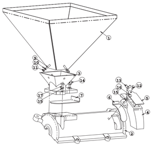
Rep. Qty. Number Name Material Standard 1 1 04-001 supply hopper steel St 37 2 1 04-002 upper body cast iron FGL 250 3 1 04-003 supply mouth feeding gray FGL 250 4 1 04-004 exit mouth cast iron FGL 250 5 1 04-005 exit sheet for inspection steel St 37 6 1 04-006 closure sheet for exit steel St 37 7 1 04-007 closure sheet steel food St 37 8 2-axis joint body felt 9 4 hexagonal screws M8 x 30 Ac 8.8 DIN 933 10 4 washer M8 Ac 8.8 DIN 125A 11 4 hexagonal nut M8 Ac 4.6 DIN 934 12 1 hexagonal screws M8 x 16 Ac 8.8 DIN 933 13 1 ears screws M8 x 16 DIN 316 Ac 8.8 GT 14 1 ear screws M10 x 20 DIN 316 Ac 8.8 GT 15 3 washer M10 Ac 4.6 DIN 125A 16 1 hexagonal screws M10 x 25 Ac 8.8 DIN 933 17 2 hexagonal screws M10 x 40 Ac 8.8 DIN 933 Note: See the table with standards for the metals in Appendix 3.
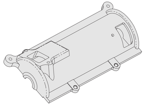
The upper body is a kind of lid that can open the machine without the need of disassembling it. This assembly also includes feeding systems and release systems for the rice.
The supply hopper[edit | edit source]
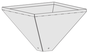
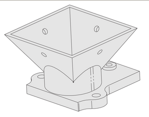
(Rep.1, see Appendix 1, drawings 04-001) It's in the hopper that we put the non-hulled rice. It allows to load a large quantity of rice in a single drop, avoiding the user to having to load the hopper continuously. This procedure also avoids the phenomenon of uprising due to the rotation of the screw.
The hopper is mechanically welded.
The upper body[edit | edit source]
(Rep.2, see Appendix 1, drawing 04-002) This piece is the "lid" of the sheller. It also permits to provide maintaintenance to the feeding and release devices. This piece is molded in cast iron and has no particular mechanical features.
The raw part must undergo several modifications: Milling of the lower surface to ensure a certain sealing with the lower body. Several holes are drilled on a template. The detailed drawings of this template can be found in Appendix 2, drawing A3-000.
The supply mouth[edit | edit source]
(Rep.3, see Appendix 1, drawing 04-003) This piece serves as a support for the hopper. It also permits to control the input flow via the closing feeding sheet (Rep.7 see Appendix 1, drawing 04-007). This piece is molded in cast iron and should has no particular mechanical feature.
The bottom surface is milled to ensure a proper contact with the body of huller. The different fixation holes are made by the drill on template. One of these holes must also be tapped.
The exit mouth[edit | edit source]
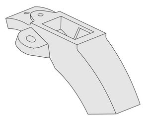
(Rep.4, see Appendix 1, drawing 04-004) This piece is designed to ensure ideal release conditions for the hulled rice. The relative high position of this piece in relation to the cylinder allows to separate the rice mixture of the chaff and sound, since only the heavier grain, are dragged up to that height.
This component also supports two adjustment pieces for the exit: the control sheets (Rep.5, see Appendix 1, Plan 04-005) and the closing sheets for the exit (Rep.6 see Appendix 1, drawing 04-006).
Several holes are made with the drill on template. Detailed drawings of this template are found in Appendix 2, drawing A5-000.
Parts to buy[edit | edit source]
Some parts are not feasible to create for a workshop (or their production cost would be too expensive), as we have previously stated. Therefore, we offer below the details of suppliers and the references of the pieces, within the limits of the currently available information at the time ofwriting. You can also contact the Belgian A.S.B.L. Codéart (see details on page 5).
Sieve Drawing: No. 02-008 Features: 1.5 x 228 mm x 215 Abwicklung Material: Steel St 12-03 Supplier: Pope & Heidersdorf Gmbh & Co Angerburg Strasse 21 22,047 Hamburg - Wandsbek Germany Tel: +49 40 694 49 50 Fax: +49 40 695 01 40 Quantity per huller: 1 Unit price: 12 euros ~
Joint Drawing: No. 03-007 Description: Washer of waterproof leather Features: dia. 138 x 39 x 4 mm Supplier: Fouilleul S.A. 50 rue du Gué-d'Orger 53 000 Laval France Tel: +33 2 43 02 96 00 Fax: +33 2 43 02 85 92 Quantity per huller: 2 Unit price: ~ 2.90 euros
Bearings Description: bearing en fonte à semelle serrage by manchet Features: NTN UKP209 Quantity per huller: 2
Kit thightening manchon Description: kit thightening manchet for the bearing UKP209 Features: NTN H2309X Quantity per huller: 2
Drivetrain[edit | edit source]
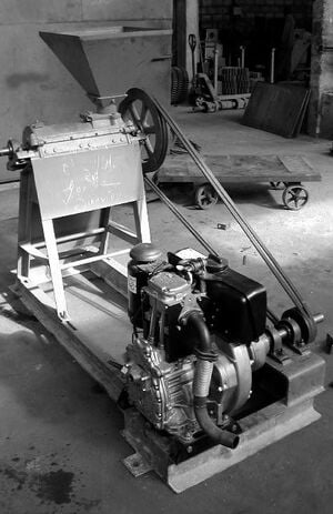
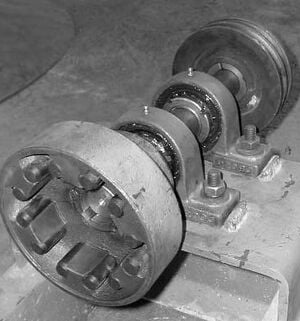
The sheller can be powered either by an electric motor, or by a diesel engine. The power required is almost 15CV or 11kW. The transmission is made by V-belt, the diameter of the driving pulley is chosen so as to have a rotor speed between 600 and 800 rpm.
The engine is used at AECP is a Hatz engine (http://www.hatz.com). This diesel engine is often used on agri-food machines and rural areas. Like many others, it is not designed to withstand a radial tension on its axis, other than the tension of the belt induces a radial load on the pulley. With this type of engine, the pulley can not be mounted directly on the engine axis. We thus use for this case a coupling attached to the two intermediate bearings and support the driving pulley. This assembly is connected to the engine by a flexible coupling to correct a margin of misalignment.
In areas where this is possible, we could also use electric engines. These requires no special maintenance.
The production of the templates[edit | edit source]
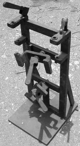
The drawings of most templates used in Camp Perrin for the drilling of the parts are grouped in Apendix 2. These templates can be modified without any problem using the available materials in the workshop at the time of their manufacturing. Only a few dimensions for constructions (mostly the placement of the drilling guns) must be respected. Of the drawings presented here, the tightening of the clames is done by standard hexagonal screws. We can improve this system by tightening the clames through eccentric screws (see Figure 34). This device allows a faster assembly and disassembly of the workpieces.
We could of course also consider building the hullers without the use of these templates, by measuring and counter-piercing the assembly, since most of the drillings do not require a very high accuracy. However, the drilling is done much more quickly using the templates. In addition, another favorable argument is that through the templates, all parts are identical, which allows you to standardize the parts and facilitate maintenance.
Maintenance[edit | edit source]
The only regular maintenance that the huller requires is the lubrication of the bearings. Cleaning the inside of the machine is also recommended. Ideally, worn parts must be replaced as soon as the performance of the machine starts to fall due to their aging. These parts are mainly the knife, the primary hulling cylinder and to a lesser extent, the secondary hulling cylinder. We estimate that the first two elements listed must be replaced after a production of about 300 tonnes of husked rice. The sieve and the fixation bars (with the adapted settings of the screws) will also need to be replaced from time to time.
The engine, whether electric or thermal, should be objected to regular maintenance of the type that is usual for such machines. The engine should not suffer from failures if it is properly used and maintained. Nevertheless, we must be careful to keep the facility from being suspended because of the engine (most frequent case). It is thus desirable to get enough spare parts in advance, at least sufficient to allow a rapid fixing of the engine by a local manufacturer (the common parts of a diesel engine are segments, pistons, crankshafts, rods, injectors, pumps...) Regarding electrical engines, there is no special maintenance except for the periodic cleaning of the cooling fins. Also check up on the magnetic-thermal circuit breaker.
Bibliography[edit | edit source]
- (1) Angladette A., Le riz, coll. Que sais-je?, Presses Universitaires de France, Paris,
1967, 126pp.
- (2) Cruz J.F. et Souare D., Transformation du riz en Guinée, CIRAD, Montpellier,
France, 1997, 37pp.
- (3) Juliano B.O., Le riz dans la nutrition humaine, FA0, Rome, 1994, 184pp.
Appendixes[edit | edit source]
- 1. Appendix 1: Drawings of the parts
- 2. Appendix 2: Drawings of the tools
- 3. Appendix 3: Table of the standards of the metals
- 4. Appendix 4: Table of the nutritional information of paddy rice and diagram of a rice grain
- 5. Appendix 5: Discontinued hullers