
Redwood Discovery Museum tornado

| Type | |
|---|---|
| Authors | Max Mather Ryan Bergum Sayra Montesinos Gabriela Ruelas |
| Location | Eureka, California |
| Status | Deployed |
| Years | |
| Made | Yes |
| Replicated | No |
| Uses | education, science, museums |
The Tornado exhibit was a project done by four environmental resource engineering students at Cal Poly Humboldt in the Fall of 2022 over twelve weeks. The Redwood Discovery Museum required more educational and engaging exhibits. Hence, the group of students' goal for this project was to demonstrate the formation of a vortex with circular and updraft airflow to meet the educational and engaging factors of the exhibit. This exhibit operates via a switch on the museum's bottom front chamber. Once someone activates the switch, both the ultrasonic fogger and the fan turn on, allowing the formation of a tornado.
Background
[edit | edit source]The Vortex project is an exhibit intended for the Redwood Discovery Museum in Eureka, California. The Redwoods Discovery Museum provides children with the opportunity to learn about science in a fun interactive manner. Their mission is to help children develop a lifelong passion for learning. The exhibit, developed by the Imagineers of Cal Poly Humboldt’s Engr. 215 class, was completed in December 2022.
Problem statement
[edit | edit source]The objective of the Vortex project is to provide children with a basic demonstration of how vortices can form. Figure 1-1 the Black Box diagram demonstrates the intended effect this exhibit will have.

Criteria
[edit | edit source]The criteria table shows a list of criteria the group decided to follow with 10 being the most important criterion, while 1 would be the least important. The team came to a decision, with the help of our client, to assign the weight to each criterion.
| Criteria | Description | Weight (1-10) |
|---|---|---|
| Safety | The ability of the exhibit to be operated by children and adults with no potential for harm. | 10 |
| Reliability | The ability of the exhibit to maintain its visual appeal and function with little to no maintenance over an extended period of time. | 10 |
| Cost | The cost of all materials used throughout the entire production process and the cost of maintenance while it is displayed in the museum. | 9 |
| Aesthetics | The visual appeal of the exhibit and how attractive it is to children. | 8 |
| Interactability | The opportunity for children to control when the exhibit operates. | 8 |
| Educational | The ability of the exhibit to provide children and adults a demonstration of a tornado forming. | 6 |
| Portability | The ability of the exhibit to be easily moved from one location to another within the museum. | 5 |
Prototyping
[edit | edit source]The students built the prototype at the University Cal Poly Humboldt makerspace. The goal was to create a small-scale exhibit using similar mechanical components to those used for the final design. Materials consisted of four PVC pipes, cardboard, duct tape, two 12-volt batteries, a small fan, hot glue, dry ice, saran wrap, and a bowl. The prototype had a bottom, top, and central chamber. Cardboard and duct tape were used for the construction of the second prototype. The bottom chamber was built in an octagonal shape. For the ceiling and the base of the chamber, four of the sides were 18 inches long and the other four were 12.7 inches long. The shorter sides all had outer angles of forty-five degrees. The walls were all 16.75 inches tall.
- Prototype Photos
-
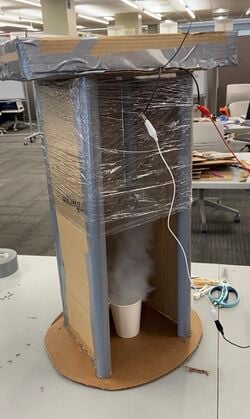 This first prototype testing functionality and attractiveness at the University of Cal Poly Humboldt
 -
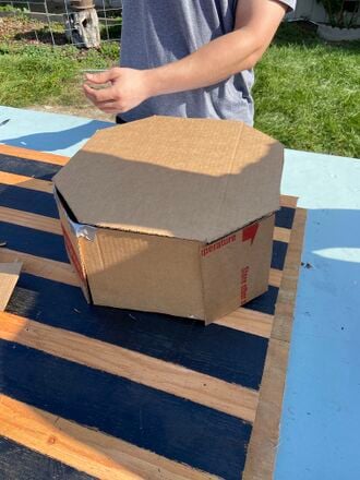 Students built the second prototype from cardboard and duct tape.


Final product
[edit | edit source]The photo below is of the completed Tornado Exhibit, composed of top and bottom octagonal chambers, connected by aluminum pipes. Clear vinyl sheets are attached in-between the pipes on the front side to seal off the main chamber where the tornado forms. While PVC sheets are used to seal off the back side. The top and bottom chambers are built entirely out of ¾in plywood. The top and bottom chambers are octagonal. Octagonal geometry was selected as a middle ground between simplicity in construction and aesthetic appeal.

The chambers are connected by 1 1/8in aluminum tubes. The bottoms of the tubes rest on the bottom face of the bottom chamber. The bottoms of the tubes are sealed to the bottom face of the bottom chamber with caulking to prevent any backflow from the top chamber. The tops of the tubes insert 3 inches into the top chamber. Each end of the tubes is secured into the chamber via a screw run through the side wall of the chamber.

The bottom chamber of the exhibit contains the ultrasonic fogger, a basin filled with water for the fogger, and a compartment housing all the electrical workings. The figure below depicts the approximate layout of the bottom chamber as well as the geometry of both the top and bottom chambers. The ultrasonic fogger creates mist which is contained within a sealed basin. A 4inch diameter tube connects the top of the basin and the central chamber of the exhibit where the vortex is formed. There are ¼ inch holes drilled in the tube which allow air to be pulled through the tube and into the central chamber along with the pooling mist. There are four 1.5inch diameter air inlets in the bottom face of the chamber to allow outside air to flow into the bottom chamber.

The top chamber of the exhibit contains the inline ventilation fan, a 6in to 4in tapered ventilation duct, and the open top sides of the aluminum tubes. The fan rests in a 7.7in diameter hole in the center of the bottom face of the chamber. The tapered ventilation duct rests directly on top of the outflow side of the fan. When the fan is turned on it pulls air from the central chamber creating an updraft. The exhaust of the fan is split by the tapered duct. Some of the exhaust is directed through the duct and out of the top chamber of the exhibit. The rest of the exhaust is directed into the sealed top chamber. The redirected airflow then travels through the open top sides of the aluminum tubes.

The central chamber consists of aluminum tubes, a vinyl sheet, and a PVC back face. The central chamber of the exhibit is mostly enclosed by a clear vinyl sheet to allow for viewing of the vortex formation. The back of the central chamber is made from PVC panels. The center panel is removable to allow access to the chamber. The center back panel also has a top to bottom slit to allow more air flow into the chamber which aids in the stability of the vortex. The aluminum tubes have 1/16 inch holes every inch for 25 inches from the bottom of the chamber. These holes allow airflow from the top chamber to be directed horizontally through the central chamber with each tube’s holes being oriented 30 degrees away from the central axis of the exhibit. The airflow from these tubes helps to create and sustain the rotation of the vortex.
The electrical loads of the tornado machine are a 400W ultrasonic fogger, an 85W inline ventilation fan, and 12V LED light strip. The fogger and fan are powered through a line voltage outlet which is in a circuit isolated from the exterior of the exhibit. The line voltage loop is routed through a GFCI and controlled by a 12V relay. A 12V, 1.3 Amp converter is plugged into the GFCI. The converter is connected to a switch which is located on the front of the exhibit. The switch controls a 12V LED light strip and a 12V relay which are run in parallel. When the switch is flipped from off to on the 12V Direct Current flows through the switch, powers the LED light strip, and flips the 12V relay. When the relay is flipped the AC line voltage side of the circuit is powered, and the fan and fogger turn on.

Construction
[edit | edit source]Steps:
- First cut out 4 octagonal pieces of plywood, with the longer four sides measuring 18" and the shorter corners measuring 13". There should be 45 degree angles between each cut.
- Next, cut out the side panels for the octagonal bases. For the longer side panels, they should measure 18" across and 16" tall, each side of the 18" length should have 22 degree cuts. For the short corner panels, they should be 13" by 16", and should also have 22 degree cuts on each side of the 13" lengths.
- After cutting the sides and faces, screws and wood glue was applied to attach the pieces together, and a ratchet was utilized to secure and tighten the pieces, as seen in the figure 1.
- Cut the aluminum pipes to 4.5' in length. Starting from 16" up, drill holes 1" apart for about 20", making sure they are in a straight line.
- Drill eight holes in top and bottom chambers for aluminum pipes to fit into, this is how the top and bottom chambers will be attached. Make sure the holes are as close to the edge as possible, so when the pipes are slipped through the holes, they are as flush as possible with the side panels of the chambers, as seen in figure 2.
- Attach top and bottom chambers together. First put the pipes all the way down into the bottom chamber, until they are resting on the bottom of the chamber. Next, put the top chamber on top of the pipes, letting the pipes slide only a few inches into the top chamber. Pre-drill holes through the wood chambers and pipes, this will make running the screws through much easier.
- Caulk inside both chambers along the edges, to seal off any possible airflow.
- Cut a hole in the top chamber and bottom chamber parallel to each other where the fog and updraft would come through, but cut an extra hole on the top chamber to allow the updraft to escape.
- To avoid degradation from water damage, we spray-painted the outside and inside of the project with black paint.
- Tilled the exhibit to drill in four casters.
- We cut sheets of clear vinyl to cover three sides of the aluminum pipes simultaneously. Leave three sides of the back of the exhibit open for PVC sheets.
- Install three PVC sheets on the back of the exhibit with velcro. The middle sheet should have a two inch slit along the left side of the sheet like on figure 3.
- Cut a small hole for the switch on the front of the bottom chamber.
- Install the electrical components on the inside of the bottom chamber. Make sure the box containing the electrical components is sealed and spray painted. Drill a small wire hole on the bottom of the box.
- Install hinges on the top and bottom chamber and use velcro to secure the lid.
- If desired install LED lights around the bottom chamber and connect it to the inside with the electrical components.
-
Figure 1) While constructing the top and bottom chamber, the group used a ratchet strap to tighten and hold the sides while the adhesive set.
-
Figure 2) The bottom chamber holding the aluminum pipes in place
-
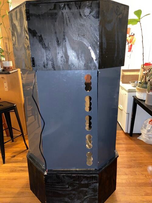 Figure 3) To maximize circular airflow we drilled holes along the left side of the middle sheet.

Video instructions
[edit | edit source]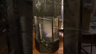
Bill of materials
[edit | edit source]The table below lists the cost of materials used in the construction of the Vortex Exhibit. The team had a total of $500 to spend. The Redwoods Discovery Museum provided the team $200 and each team member was asked to contribute $75 in the case where the $200 was not enough to cover construction costs. Not all materials used were bought, the aluminum pipes were donated by the Arcata Scrap and Salvage Yard and the plywood was donated by Scott Bergum. The Vortex Exhibit cost a total of $360.18 to construct.
| Item | Amount | Cost per unit | Total |
|---|---|---|---|
| Fan — 500 CFM Inline fan[1] | 1 | USD 86.79 | USD 86.79 |
| Fogger — 12 head ultrasonic fogger[2] | 1 | USD 119.24 | USD 119.24 |
| Vinyl — 25ft roll | 1 | USD 32.54 | USD 32.54 |
| Casters — 1 1/2 in | 4 | USD 9.99 | USD 39.96 |
| Caulking — All weather proof | 1 | USD 8.59 | USD 8.59 |
| Spray Paint — black | 4 | USD 9.32 | USD 37.28 |
| All purpose glue — All weather proof | 1 | USD 8.67 | USD 8.67 |
| LED — blue | 1 | USD 18.45 | USD 18.45 |
| Hinges — pack of two | 2 | USD 4.33 | USD 8.66 |
| Plywood(donated) — 72 sq. ft | 1 | USD 0.00 | USD 0.00 |
| Aluminum Pipes(donated) — 45 ft | 8 | USD 0.00 | USD 0.00 |
| Electrical components (donated) | 1 | USD 0.00 | USD 0.00 |
| PVC sheets — 4' x 4 ' | 1 | USD 0.00 | USD 0.00 |
| Grand total | USD 360.18EUR 309.75 <br />GBP 262.93 <br />CAD 446.62 <br />MXN 7,509.75 <br />INR 26,959.47 <br /> | ||
Operation
[edit | edit source]The tornado exhibit is extremely simple to operate, simply make sure the power cord is plugged in, check the water level in the bottom chamber, and flick the switch to turn on the fan and fogger.

Open bottom chamber, pull out bin used for water, make sure the ultrasonic fogger is submerged under water.

Power cord is located at the back of the exhibit, coming out from the bottom chamber. Once plugged in, flick switch located on the front of the bottom chamber to turn fan and ultrasonic fogger on.
Maintenance
[edit | edit source]The Tornado Exhibit requires minimal maintenance. The ultrasonic fogger must be refilled once it is empty. The operator will be aware of when it has run out of water since it will shut off automatically. The only maintenance cost will essentially be the cost of operation, this includes the cost of electricity and the cost of water. Since the Vortex Exhibit will only be running around 5 hours a week, the weekly cost of operation will be around eighty-two cents. The cost of operation is displayed in the table below.
| Estimated Cost of Maintenance for 5 hrs/week | |||
|---|---|---|---|
| Product | Cost of Electricity/Week ($) | Cost of Water/Week ($) | Total Cost Week/ Product ($) |
| Fogger | 0.68 | 0.02 | 0.70 |
| Fan | 0.14 | N/A | 0.14 |
Maintenance schedule
[edit | edit source]- Daily
- Fill bottom chamber bucket with water when needed
- Clean the exhibit if too much condensation occurs
- Monthly
- Make sure the fogger and fan is working adequately.
- Yearly
- Make sure plywood is holding up
- Every 2 years
- Replace the fogger/fan if needed
Conclusion
[edit | edit source]Testing results
[edit | edit source]- Testing the switch's on and off function - We tested the switch by ensuring the fan and fogger start when flicked up and shut down when flicked down.
- Testing how much water the fogger goes through every f10 minutes. - When testing how much water the fogger goes through, we measured the volume of the water in a 16 1/2 inch by 8 1/2 inch bucket on time zero, ran the fogger for ten minutes, and measured the volume of water to waste less the 1/16 of an inch of water every 10 minutes.
- Testing how much power the fan pulls- [waiting for instrument]
- Testing the circular airflow through the aluminum pipes- To figure out what direction the aluminum pipes should face, we moved them while the exhibit was on to see which direction formed a tighter vortex.
Discussion
[edit | edit source]After testing our exhibit, we learned we needed to come up with an easier way of pouring in water into the chamber.
Lessons learned
[edit | edit source]Something we would do differently is more research devoted to moisture control when working with foggers in enclosed spaces. Investigate how different tornado exhibits do for moisture control.
Next steps
[edit | edit source]In the future, with the help of donations, the Redwood Museum can replace the clear vinyl with acrylic plastic and come up with a less complicated way pour water into the bottom chamber.
Troubleshooting
[edit | edit source]| Problem | Suggestion |
|---|---|
| The vortex is not forming but the power for both fan and fogger is on. | Make sure the speed control on the fan is on medium. |
| For aesthetic purposes if water is dripping from the fan | Take out the fan and dry it |
| The vinyl is foggy | Wipe it from the inside with a rag. |
Team
[edit | edit source]Imagineers - F22
References
[edit | edit source]| Authors | |
|---|---|
| License | CC-BY-SA-4.0 |
| Organizations | Cal Poly Humboldt Paper Towel Diversion Project Phase II |
| Cite as | Lonny, Max Mather, SayraM (2022–2024). "Redwood Discovery Museum tornado". Appropedia. Retrieved July 27, 2026. |