
Deformity Correction of Lower Limb Bones/Surgery Planning
To perform complex bone deformity corrections successfully, the pre-op planning of the surgery on x-ray images is very important. The x-ray based surgery planning of deformity correction is very crucial in assessing and correcting the complex deformity. The surgery planning consists of drawing various anatomical axis lines on the x-ray showing the deformed bone and simulating the resection and repositioning of the resected bone segments. This process creates some surgical knowledge/parameters which then need to be applied on the physical bone.
The Surgery Planning Sub-Modules of OpenSurgiSim are specifically designed for trainee orthopaedic surgeons to learn how to perform pre-op surgery planning of long bone deformities and simulate the deformity correction. It will train all the aspects of surgery planning and determining the surgical knowledge/parameters like accurate deformity assessment (understanding the deformity and its extent in quantifiable terms), correction scenarios (determining correct bone resection site and positioning of resected bone parts), outcomes and post-operative correction simulation (the deformity correction) and finally the implant application (determining correct position and orientation of the fixator implant's pins).
The Surgery Planning Sub-Modules has 18-20 real-patient cases to practice the surgery planning. The OpenSurgiSim automatically assess the performance and show its analysis to the trainee as well as given in the Self-Assessment section below.
How to use the Surgery-Planning Sub-Module
[edit | edit source]The following video will help trainees to understand how to use the Surgery-Planning Training Sub-Module (Guided Sub-Module):
Main page
[edit | edit source]The Surgery Planing is given in two forms (sub-modules) Guided and Non-Guided. The idea is that the trainee first undergo training with the guidance from the trainer (Planning-Guided sub-module) and then perform the planning herself/himself without the guidance (Planning-Non-Guided sub-module), to assess her/his own skill. To access the Planning-Guided or Planning Non-Guided sub-modules, the Trainee has to click corresponding buttons at the top of the OpenSurgiSim main page. Within each sub-module, the case-studies are arranged within 10 expandable/collapsable sections called as categories, according to the type of case. Each category may have two or more numbers of case-studies as rows of table (total 18-20 cases in both the sub-modules). Each case-study include real patient x-ray case which has been pre-planned by an expert trainer surgeon. Clicking on the row will open the case-study and show its preview on the right-side. Clicking on 'Expand' button (second from top-right, below the 'Home' button) will open the case-study in full screen, as shown below.

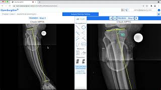
Once the case-study is opened the trainee will find the following user-interface (figure below) explained below with the figure.
a) There are two panels namely - Trainer (on left) and Trainee (on right). On both the panels, the deformity case x-ray is visible on a canvas, onto which annotations to be drawn and measurements to be made for planning the surgery.
b) The trainer side panel displays the x-ray with pre-planned annotations and measurements through multiple steps. The trainee has to follow each step sequentially as given on the right side Trainee panel.
c) To navigate through the planning steps, trainee can click the navigation arrows buttons at the top title bar.
d) The trainee can click on 'AP-LAT' button to toggle between the two x-rays (if available). In this module however, the cases are single-planar deformities which need only AP or only LAT x-ray images to plan the surgery.
e) There is an Annotation-panel in the middle section which has all the necessary annotation drawing tools and measurement for planning a case.
f) The trainee can click on any annotation tool icon to enable the selection and hence the use of that particular tool. After any tool has been selected, the trainee can right-click on the x-ray image canvas in he trainee panel to disable the selection of the tool.
g) The trainee can select any annotation already drawn on the canvas by clicking on the annotation on the x-ray image canvas. The drawing tool properties of the selected drawing appears in the top-left corner. These properties includes color, line thickness, etc.

In a case-study under the Planning-Guided sub-module, the expert/trainer's surgery plan will be displayed to the trainee on the left side Trainer panel, as shown above. The Trainee can perform planning on the right side Trainee panel by following the step by step guidance on the left.
In a case-study under the Planning-Non-Guided sub-module the expert/trainer's surgery plan on the left side Trainer panel will be hidden and the Trainee will perform planning herself/himself.
Annotation tools for surgery planning
[edit | edit source]The following is a list of annotation and measurement tools and their usage in the planning software module. Information and guidelines on how to use the annotation tools to plan the surgery on the patient's x-ray, is given in the OpenSurgiSim with the title Basic Planning case-studies.

1) Circular calibrator: This tool is used to calibrate (measure Xray scale) an Xray image by drawing circle using three points. On clicking this tool icon, user has to place first, second and third points of the circle by clicking on the periphery of the circular calibrator object.

The following example illustrates how to use the 3-point Circular calibrator tool to draw and calibrate the X-ray images.
Step 1: Select 'Circular calibrator' tool from Annotations panel.
Step 2: Click on the periphery of the circle calibrator object on xray to select the first, second and third point.
Step 3: In the calibrator tool properties, fill the calibrator size field box with 30 value since the calibrator ball diameter of 30 mm was used while taking this xray.

In this tool Dialog box, there are various properties of the drawing which can be modified as required.
a) The user can label this drawing by typing the name in the empty 'add name' box.
b) The user can highlight the drawing by selecting the 'Highlight' checkbox. The user can animate (on-off) the drawing by selecting the 'Animate' checkbox.
c) The user can put the value of the diameter of calibrator object in calibrator size box.
d) The user can change the size of the thickness of the drawing by changing the value of width option.
e) The user can select the color of the Line by selecting the RGB values or the color picker from the 'Line color' option.
f) The user can select the color of the points which makes this drawing by selecting the RGB values or the color picker from the 'Point color' option
g) The user can delete this drawing by clicking on cross (X) button on top.

2) Line calibrator: This tool is used to calibrate (measure Xray scale) an Xray image by drawing line using two points. On clicking this tool icon, user has to place first, and second points of the line by clicking on the two edges of the line calibrator object.

The following example illustrates how to use the 2-point Line calibrator tool to draw and calibrate the X-ray images.
Step 1: Select 'Line calibrator' tool from Annotations panel.
Step 2: Click on the periphery of the line calibrator object on xray to select the first and second point.
Step 3: In the calibrator tool properties, fill the calibrator size field box with 100 value since the calibrator length of 100 mm was used while taking this xray.

In this tool Dialog box, there are various properties of the drawing which can be modified as required.
a) The user can label this drawing by typing the name in the empty 'add name' box.
b) The user can highlight the drawing by selecting the 'Highlight' checkbox. The user can animate (on-off) the drawing by selecting the 'Animate' checkbox.
c) The user can put the value of the length of the calibrator object in calibrator size box.
d) The user can change the size of the thickness of the drawing by changing the value of width option. The user can change the size of the thickness of the written text in the drawing by changing the value of Font option.
e) The user can select the color of the Line by selecting the RGB values or the color picker from the 'Line color' option.
f) The user can select the color of the points which makes this drawing by selecting the RGB values or the color picker from the 'Point color' option
g) The user can delete this drawing by clicking on cross (X) button on top.

3) 2-Point Line: This tool is used to generate a line by connecting two points. On clicking this tool icon, user has to place first and second points of the line by clicking on the image at the required positions.

The following example illustrates how to use the 2-point Line tool to draw Proximal Femur Jointline on X-ray images.
Step 1: Select '2-point Line' tool from Annotations panel.
Step 2: Click on the tip of the greater trochanter to select the first point.
Step 3: Click on the femur head circle centre to select the second point.

In this tool Dialog box, there are various properties of the drawing which can be modified as required.
a) The user can label this drawing by typing the name in the empty 'add name' box.
b) The user can highlight the drawing by selecting the 'Highlight' checkbox. The user can animate (on-off) the drawing by selecting the 'Animate' checkbox.
c) The user can select whether the second end of this line should be a point or an arrow.
d) The user can change the size of the thickness of the drawing by changing the value of width option. The user can change the size of the thickness of the written text in the drawing by changing the value of Font option.
e) The user can select the color of the Line by selecting the RGB values or the color picker from the 'Line color' option.
f) The user can select the color of the 2 points which makes this line by selecting the RGB values or the color picker from the 'Point color' option
g) The user can delete this drawing by clicking on cross (X) button on top.

4) 3-Point Circle:

The following example illustrates how to use the 3-point Circle tool to draw Proximal Femur Ballhead on X-ray images.
Step 1: Select '3-point Circle' tool from Annotations panel.
Step 2: Click three points around the periphery of Femoral ball to complete the circle.

In this tool Dialog box, there are various properties of the drawing which can be modified as required.
a) The user can label this drawing by typing the name in the empty 'add name' box.
b) The user can highlight the drawing by selecting the 'Highlight' checkbox. The user can animate (on-off) the drawing by selecting the 'Animate' checkbox.
c) The user can change the size of the thickness of the periphery by changing the value of 'Width' option.
d) The user can select the color of the circle by selecting the RGB values or the color picker from the 'Line color' option.
e) The user can select the color of the 3 points which makes this circle by selecting the RGB values or the color picker from the 'Point color' option
f) The user can delete this drawing by clicking on cross (X) button on top.

5) 4-Point Line:

The following example illustrates how to use the 4-point Line tool to draw Femoral Proximal Anatomical Axis on X-ray images.
Step 1: Select '4-point Line' tool from Annotations panel.
Step 2: Click and place two points of first line segment on two cortex ends of proximal shaft.
Step 3: Click and place two points of second line segment on two cortex ends of distal shaft.
Step 4: Click anywhere in femur mid-shaft region to complete the line
In this tool Dialog box, there are various properties of the drawing which can be modified as required.
a) The user can label this drawing by typing the name in the empty 'add name' box.
b) The user can highlight the drawing by selecting the 'Highlight' checkbox. The user can animate (on-off) the drawing by selecting the 'Animate' checkbox.
c) The user can select whether the second end of this line should be a point or an arrow.
d) The user can change the size of the thickness of the drawing by changing the value of 'Width' option. The user can change the size of the thickness of the written text in the drawing by changing the value of 'Font' option.
e) The user can select the color of the Line by selecting the RGB values or the color picker from the 'Line color' option.
f) The user can select the color of the 4 points which makes this line by selecting the RGB values or the color picker from the 'Point color' option
g) The user can delete this drawing by clicking on cross (X) button on top.

6) Bisector Line:

The following example illustrates how to use the Bisector Line tool to draw bisector line of Proximal and Distal Femoral Anatomical Axis Lines on X-ray images.
Step 1: Select 'Bisector Line' tool from Annotations panel.
Step 2: Click the Proximal Anatomical Axis line to select the first line
Step 3: Click the Distal Anatomical Axis line to select the second line

In this tool Dialog box, there are various properties of the drawing which can be modified as required.
a) The user can label this drawing by typing the name in the empty 'add name' box.
b) The user can highlight the drawing by selecting the 'Highlight' checkbox. The user can animate (on-off) the drawing by selecting the 'Animate' checkbox.
c) The user can change the size of the thickness of the line by changing the value of 'Width' option.
d) The user can change the length of the line by changing the value of 'Length' option.
e) The user can select the color of the Line by selecting the RGB values or the color picker from the 'Line color' option.
f) The user can change the position of the angle bisector to be placed between the 2 selected lines by toggling (consecutively clicking) the 'position' button.
g) The user can delete this drawing by clicking on cross (X) button on top.

7) Line Parallel to Line:

The following example illustrates how to use the Line parallel to Line Tool to draw a line parallel to Proximal Femoral Anatomical Axis Line on X-ray images.
Step 1: Select 'Line parallel to Line' tool from Annotations panel.
Step 2: Click and select the reference line to which parallel line is to be drawn.
Step 3: Select first point of the parallel line at the femur head centre.
Step 4: Select second point of the parallel line anywhere near the femur central shaft region.
In this tool Dialog box, there are various properties of the drawing which can be modified as required.
a) The user can label this drawing by typing the name in the empty 'add name' box.
b) The user can highlight the drawing by selecting the 'Highlight' checkbox. The user can animate (on-off) the drawing by selecting the 'Animate' checkbox.
c) The user can select whether the second end of this line should be a point or an arrow.
d) The user can change the size of the thickness of the drawing by changing the value of 'Width' option. The user can change the size of the thickness of the written text in the drawing by changing the value of 'Font' option.
e) The user can select the color of the Line by selecting the RGB values or the color picker from the 'Line color' option.
f) The user can select the color of the 2 points which makes this line by selecting the RGB values or the color picker from the 'Point color' option
g) The user can delete this drawing by clicking on cross (X) button on top.

8) Line at Angle:

The following example illustrates how to use the Line at Angle Tool to draw Proximal Reference Mechanical Axis line at an angle to Proximal Femoral Jointline on X-ray images.
Step 1: Select 'Line at Angle' tool from Annotations panel.
Step 2: Select the reference line (proximal jointline) in relation to which another line at an angle is to be drawn
Step 3: Click away from first point to select the second point of new line.
Step 4: In line at angle tool properties, input ratio value as 1 or 0 to move the first point to femur head centre end of the proximal jointline.
Step 5: Keep clicking the position button in angle line tool properties box till angle position is lateral. Input angle value as 90 deg.

In this tool Dialog box, there are various properties of the drawing which can be modified as required.
a) The user can label this drawing by typing the name in the empty 'add name' box.
b) The user can highlight the drawing by selecting the 'Highlight' checkbox. The user can animate (on-off) the drawing by selecting the 'Animate' checkbox.
c) The user can change where the drawn line should start w.r.t reference line. For midpoint, input the value in 'ratio' box as 0.5
d) The user can change the value of the angle by changing the value in 'Value' textbox.
e) The user can change the size of the thickness of the drawing by changing the value of 'Width' option. The user can change the size of the thickness of the written text in the drawing by changing the value of 'Font' option.
f) The user can change the diameter of the angular arc by changing the value of 'Dia' option.
g) The user can select the color of the drawing by selecting the RGB values or the color picker from the 'Line color' option.
h) The user can change the position of the angle to be measured between the 2 selected lines by toggling (consecutively clicking) the 'position' button.
i) The user can select the color of the points which makes this drawing by selecting the RGB values or the color picker from the 'Point color' option
j) The user can delete this drawing by clicking on cross (X) button on top.

9) Open-wedge:

The following example illustrates how to use the Open-wedge Tool to simulate open-wedge correction on X-ray images.
Step 1: Select 'Open-wedge' tool from Annotations panel.
Step 2: Click on CORA to place the ACA (pivot) point. The resected distal bone segment always rotates about ACA point during Deformity Correction
Step 3: Click on convex bone cortex to place the first point and concave cortex to place second point of resection line
Step 4: Input angle value and Click on Activate button in tool Dialog box to simulate the correction.

In this tool Dialog box, there are various properties of the drawing which can be modified as required.
a) The user can label this drawing by typing the name in the empty 'add name' box.
b) The user can highlight the drawing by selecting the 'Highlight' checkbox. The user can animate (on-off) the drawing by selecting the 'Animate' checkbox.
c) The user can draw the contour of distal bone fragment to be repositioned and realigned after osteotomy by selecting the 'Contour' checkbox.
d) The user can change the value of the osteotomy correction angle by changing the value in 'Rotation' textbox.
e) The user can change the size of the thickness of the drawing by changing the value of 'Width' option.
f) The user can select the direction of rotation of the resected distal bone fragment by clicking on 'clockwise' or 'anticlockwise' icon in the 'Rotation' option.
g) The user can select the color of the drawing by selecting the RGB values or the color picker from the 'Line color' option.
h) The user can simulate this wedge correction by clicking on 'Activate' button. The distal resected bone segment is corrected by the correction angle value inserted in the 'Rotation' textbox.
i) The user can select the color of the points which makes this drawing by selecting the RGB values or the color picker from the 'Point color' option.
j) The user can delete this drawing by clicking on cross (X) button on top.
10) Bone Contour:

The following example illustrates how to use the Bone Contour Tool to draw Distal Femoral Bone segment outline on X-ray images.
Step 1: Select by clicking on the 'open-wedge' line drawn on the Xray. Let's draw the contour of distal fragment for this open-wedge cut.
Step 2: In the open-wedge tool properties, select the Contour checkbox. The contour will appear at random place.
STEP 3: Click and drag the end points of the contour to cover the distal femur completely inside the contour area.
11) Activate Resection:

The following example illustrates how to use the wedge tool properties to resect and reposition the Distal Bone segment outline on X-ray images.
Step 1: Select by clicking on the 'open-wedge' line drawn on the Xray. Let's activate the open wedge resection line (perform resection and reposition distal bone fragment)
Step 2: In the open-wedge tool properties, put in the correction angle value in rotation field as measured in the previous steps.
Step 3: Select the direction (clockwise) and click on 'Activate' button to reposition the resected distal femur in clockwise manner. Select anticlockwise direction if you want to rotate the other way.

12) Length Tool:

The following example illustrates how to use the Length Tool to measure osteotomy gap on X-ray images.
Step 1: Select 'Length' tool from the Annotations panel.
Step 2: Click on the convex cortex end of the resected proximal femur fragment to select the first point
STEP 3: Click on the convex cortex end of the resected distal femur fragment to select the second point. The length measurement will now appear.
In this tool Dialog box, there are various properties of the drawing which can be modified as required.
a) The user can label this drawing by typing the name in the empty 'add name' box.
b) The user can highlight the drawing by selecting the 'Highlight' checkbox. The user can animate (on-off) the drawing by selecting the 'Animate' checkbox.
c) The user can view the value of the line length in the 'Value' textbox.
d) The user can change the size of the thickness of the drawing by changing the value of 'Width' option. The user can change the size of the thickness of the written text in the drawing by changing the value of 'Font' option.
e) The user can select the color of the drawing by selecting the RGB values or the color picker from the 'Line color' option.
f) The user can select the color of the points which makes this drawing by selecting the RGB values or the color picker from the 'Point color' option
g) The user can delete this drawing by clicking on cross (X) button on top.

13) Angle Tool:

The following example illustrates how to use the Angle Tool to measure angle between Proximal and Distal Femoral Anatomical Axis on X-ray images.
Step 1: Select 'Angle' tool from Annotations panel.
Step 2: Click on Proximal Anatomical Axis line to select the first line.
Step 3: Click on Distal Anatomical Axis line to select the second line.
Step 4: The angle position can be changed by clicking on position in the Angle Dialog box.

In this tool Dialog box, there are various properties of the drawing which can be modified as required.
a) The user can label this drawing by typing the name in the empty 'add name' box.
b) The user can highlight the drawing by selecting the 'Highlight' checkbox. The user can animate (on-off) the drawing by selecting the 'Animate' checkbox.
c) The user can view the value of the angle in the 'Value' textbox.
d) The user can change the size of the thickness of the drawing by changing the value of 'Width' option. The user can change the size of the thickness of the written text in the drawing by changing the value of 'Font' option.
e) The user can change the diameter of the angular arc by changing the value of 'Dia' option.
f) The user can select the color of the drawing by selecting the RGB values or the color picker from the 'Line color' option.
g) The user can change the position of the angle to be measured between the 2 selected lines by toggling (consecutively clicking) the 'position' button.
h) The user can delete this drawing by clicking on cross (X) button on top.
Self-Assessment and Scores
[edit | edit source]Question Types
[edit | edit source]At every critical step of the planning, the software will present assessment questions. Based on the answer provided by the trainee, a performance score is calculated for the particular case. There will be three kind of assessment questions:

True-False Questions: The assessment question can be a simple True or False type question. A score of 10 is given for the correct answer and 0 for the incorrect one.

Multiple Choice Questions: The assessment question can be a multiple choice question with a single solution. The answer can be a numeric value (angle/distance) or text related to some decision making or diagnosis. A score of 10 is given for the correct answer and 0 for the incorrect one.

General Questions: The assessment question can be a simple question with only one possible answer - a single number or a word. Here the answer will always be a numeric value (angle/distance) and based on the difference between the trainee's answer and the correct answer a score between 0 to 10 is generated.
Case performance chart
[edit | edit source]
This can be accessed at the end of the case planning. The chart will showcase trainee's answers and the correct answers for each question and its related score. Trainee can also go back to any question and its related step in the surgery planning very easily, from the chart. An overall Case-Score is generated by averaging the scores of all the assessment questions.
Assessment pathway
[edit | edit source]
Case Score and Case Completion Level
[edit | edit source]For each case within a case-study category, there will be a number of assessment questions and the Trainees will be assigned scores based on the number of assessment question they answer correctly for that particular case. This score is known as Case Score. A Case Completion Level (in terms of percentage) will be assigned depending on number of guided steps which Trainees have finished within that particular case.
Category Score and Category Completion level
[edit | edit source]A case-study category consists of a number of cases. Hence, a Category Score is an average of all the Case Scores of the cases within that selected category. Similarly, a Category Completion Level (in terms of percentage) is an average of all the Case Completion Levels within that selected category.
Sub-module Score and Sub-module Completion level
[edit | edit source]A sub-module consists of a number of case-study Categories. Hence, a Sub-module Score is an average of all the Category Scores (score of the categories within that selected Sub-Module). Similarly, a Sub-module Completion level (in the form of percentage) is an average of all the Category Completion Levels within that selected module.
How this measured performance of the learned skill will translate into its clinical performance
[edit | edit source]The measured performance of the skills which are learned through practicing on the case studies of Guided as well as Non-Guided Sub-Modules (like assessing the deformity, accurately quantifying the deformity, simulating the correction on X-ray etc.) will translate directly into its clinical performance because the case-studies are the real-patient X-ray images. In addition, the case studies are carefully and uniquely selected by expert surgeons to cover all the range of basic lower-limb bone deformity corrections. Practicing so many times on all kinds of deformity cases will train the surgeons perfectly to perform such planning in any patient confidently and accurately. The Surgery Planning Sub-Modules trains all the aspects of surgery planning, like accurate diagnosis, deformity assessment (quantifiable terms), correction scenarios and outcomes and post-operative correction simulation. These aspects determine the surgical pathway, strategy and parameters of the surgery on real bone of the patient.
In fact, the Surgery Planning Sub-Module is designed in such a way that any surgeon in the world can upload her/his own patient's X-ray images and use the annotation tools to plan a surgery in the same way as it was practiced/trained in the sub-module itself. This feature is however locked in the current version.
| Authors | Amit Dinanath Maurya, OpenSurgiSim |
|---|---|
| License | CC-BY-SA-4.0 |
| Organizations | AlgoSurg Inc, Mangal Anand Hospital (Mumbai), OpenSurgiSim, Global Surgical Training Challenge |
| Cite as | Amit Dinanath Maurya, OpenSurgiSim (2021–2026). "Deformity Correction of Lower Limb Bones/Surgery Planning". Appropedia. Retrieved July 10, 2026. |