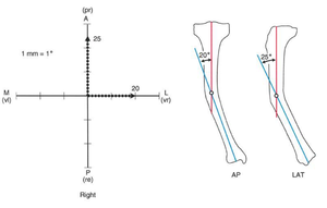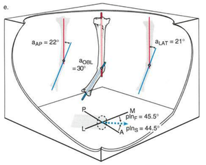
Angular deformity in long bones can occur in any plane. Deformities in which angulation is seen on both AP and LAT x-rays are actually uniapical or multiapical deformities in an oblique plane. They are also known as 'Oblique plane deformities' (Fig. 10a)
To plan an oblique plane deformity case, two important parameters are required. One is the 'angle of the oblique plane' itself w.r.t the AP and LAT direction. Second is the 'magnitude of angulation deformity' which the bone has in this oblique plane. Both these parameters can be calculated by a simple method called 'Graphical method' explained as follows.
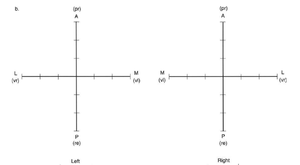
First draw a graph with orthogonal x-axis and y-axis. The x-axis represents the frontal plane (AP view) and the y-axis represents the sagittal plane (LAT view). It is drawn in such an orientation by imagining that you are viewing your own foot from the top. The plane of the graph represents the Transverse plane of the body.
The positive y-axis represents the anterior (A) side while the negative y-axis represents the posterior (P) side for both right and left leg. For the left leg, the positive x-axis represents the medial (M) side while the negative x-axis represents the lateral (L) side. For the right leg, the negative x-axis represents the medial (M) side while the positive x-axis represents the lateral (L) side. Label the graph appropriately (Fig. 10b)
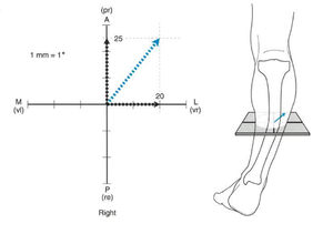
Mark the magnitude of angulation in the bone in AP and LAT view on the graph taking 1 mm = 1° as the scale. For the right leg, if AP angulation is varus (vr), mark the angular correction angle on the positive x-axis and if it is valgus (vl), it is negative x-axis. For the right leg, if LAT angulation is procurvatum (pr), mark the angular correction angle on the positive y-axis and if it is recurvatum (re), it is negative y-axis (Fig. 10c)
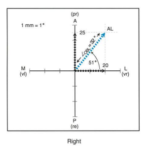
Measure the length of this newly drawn oblique line, then that value will become the 'magnitude of angulation' in the oblique plane. Measure the angle between the oblique line and the x-axis (lateral), then that value will become the 'oblique plane angle' from the front (AP) view (Fig. 10e). Now the deformity can be planned in this oblique plane like planning done in normal uniapical deformity in AP or LAT view. The 'magnitude of angulation' is the correction angle for osteotomy in this oblique plane.
