
Deformity Correction of Lower Limb Bones/Basic Principles/Mechanical and Anatomical Axis Planning
When there is malalignment or malorientation in femur or tibia bone, the bone with deformity can be divided into proximal and distal bone segments. The correction of a deformity in the frontal plane can be planned in #Frontal plane, while the correction of a deformity in the sagittal plane can be planned in #Sagittal plane.
Frontal plane
[edit | edit source]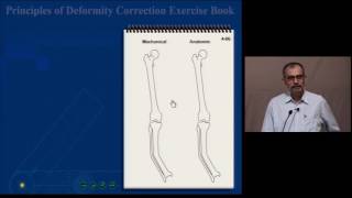

When there is Malalignment or Malorientation in femur or tibia bones, the bone with deformity can be divided into proximal and distal bone segments. The proximal and distal bone segments have their own proximal mechanical axis (PMA) or proximal anatomical axis (PAA) line and distal mechanical axis (DMA) or distal anatomical axis (DAA) line respectively (Fig. 8a)

The bone angulation deformity can be seen in either the frontal plane (visible on AP x-rays) or sagittal plane (visible on LAT x-rays) or both.
These angulation deformities can be at one level or location in the bone referred to as 'Uniapical deformity' or it can be at multiple locations also referred to as 'Multiapical deformity' (Fig. 8j)
Sagittal plane
[edit | edit source]
When there is Malalignment or Malorientation in femur or tibia bones in sagittal plane, the proximal and distal bone segments have their own proximal mechanical axis (PMA) or proximal anatomical axis (PAA) line and distal mechanical axis (DMA) or distal anatomical axis (DAA) line respectively in the sagittal plane (Fig. 9a)

Draw anatomical axis of proximal shaft and anatomical axis of distal shaft. The point of intersection of the axes is CORA and the magnitude of acute angle formed is the magnitude of correction angulation required (Fig. 9b)

Draw anatomical reference line from proximal joint line of tibia at (1/5th width of condyle) and anatomical axis of the shaft or anatomical reference line at normal ADTA angle of 80 from the distal joint line. The point of intersection of the axes is CORA and the magnitude of acute angle formed is the magnitude of correction angulation required (Fig. 9c)
| Authors | Amit Dinanath Maurya, OpenSurgiSim |
|---|---|
| License | CC-BY-SA-4.0 |
| Organizations | AlgoSurg Inc, Mangal Anand Hospital (Mumbai), Global Surgical Training Challenge |
| Cite as | Amit Dinanath Maurya, OpenSurgiSim (2021–2025). "Deformity Correction of Lower Limb Bones/Basic Principles/Mechanical and Anatomical Axis Planning". Appropedia. Retrieved July 15, 2026. |