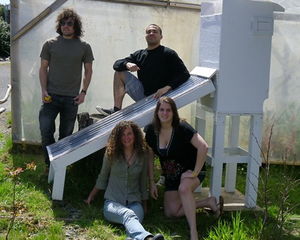
Beginning in the Spring semester of 2011, Team SodHoppers joined together to work on a semester long project assigned to them by Lonny Grafman. Their client, Locally Delicious, gave them the opportunity to design and build a solar dehydrator that will be placed in a nearby elementary school. This design will ultimately reside in Locally Delicious's new book "Lunchbox Envy," enabling schools across the country to implement the design also.
Background[edit | edit source]
Locally Delicious is a group of women collaborating on a new book titled "Lunch Box Envy." Several different Engineering 215 projects are to be included. The school solar dehydrator is one of them.
Team SodHoppers:
Objective and Criteria[edit | edit source]
Objective[edit | edit source]
The objective of this project is to make the youth that participate in this project knowledgeable about food dehydration, conservation techniques, and food sustainability.
Criteria[edit | edit source]
Several criteria were weighted and defined shown in the table below.
| Criteria | Weight | Description |
|---|---|---|
| Safety | 10 | This is defined as a structure being stable enough for children, having safe building materials for food quality, and having a completely finished project to protect children against loose material or sharp edges. |
| Cost | 9 | Design must cost less than $300. |
| Reproducible | 9 | This is defined as the ease of following the directions and constructing the solar dehydrator. |
| Durability | 8 | This is defined as having a structure that is able to last two to three years with regular use by adults and children. |
| Weather Resistance | 8 | This is defined as the structure's ability to hold up against all types of weather. |
| Ease of Use | 7 | This is defined as a structure that has a design that is easily operated on a child's level. |
| Efficiency | 7 | This is defined as the project's ability to dry food quickly and to dry the food to the operator's expectations of good quality dehydration. |
| Aesthetics | 4 | This is defined as the project with a presentable and school appropriate design. |
Description of Final Project[edit | edit source]
The project goal was to design a solar food dehydrator that would be replicated by schools around the United States.
Sunlight enters the slanted solar collector through the glazing, a polycarbonate sheet, and heats up a metal sheet. The air between the glazing and the solar collector warms, which causes it to become less dense and rise. As this air rises, it is replaced by outside air entering from the bottom of the collector which is then heated as well. The rising air eventually exits the collector and enters an insulated elevated cabinet with an air vent on the top. Since the air inside the cabinet is less dense than the outside air from being heated, it moves vertically within the cabinet and exits the cabinet through the vent. The cabinet contains horizontally oriented frames with nylon mesh in which produce is placed on. This produce dries from the moving hot air it is exposed to.
The solar collector contains a black painted copper sheet which sits on top of insulation within a polycarbonate covered wood box.
Costs[edit | edit source]
Design Hours[edit | edit source]
Figure 1: Pie Chart detailing how the SodHoppers spent their time on the project.
Material Costs[edit | edit source]
| Materials | Use | Quantity | Project Cost ($) | Projected Cost ($) |
|---|---|---|---|---|
| Small Cabinet | Dryer Box | 1 | 6.00 | 30.00 |
| Screen | Covering End of Solar Collector | 1 | 1.00 | 4.00 |
| Styrofoam Insulation | Insulation of Solar Collector | 4 | 1.52 | 60.00 |
| Copper Sheet Metal | Heat Conductor for Solar Collector | 63" X 27" | 40.00 | 40.00 |
| Metal Roof | Roofing for Weather Protection | .97 tons | 5.00 | 0.00 |
| Reflective Insulation | Insulation for Dryer Box | 5'X 4' | 22.80 | 22.80 |
| Polycarbonate | Glazing Material | 10' X 26" | 35.29 | 35.29 |
| Screws | For Polycarbonate | 1 box | 6.00 | 6.00 |
| Screws, Sealant,Latch, and Polyfoam | General Use | 1 pack | 6.95 | 6.95 |
| Sealant | Not used | 1 Tube | 7.75 | 0.00 |
| Latch | Locking Cupboard | 1 | 5.00 | 5.00 |
| Polyfoam | Sealing Polycarbonate | 1 | 3.00 | 3.00 |
| Tacks | Securing Insulation | 1 box | 1.34 | 1.34 |
| Caulking | Not used | 1 tube | 5.84 | 0.00 |
| Hinges | For Cabinet Doors | 2 packs | 9.88 | 9.88 |
| Hinges | Not used | 2 packs | 0.00 | 4.00 |
| Piping | Connecting Solar Collector | 1 | 1.00 | 1.00 |
| Nylon Mesh | Drying Racks | 3 yards | 6.06 | 6.06 |
| All Lumber | Collector Box, Drying Racks, and Base | N/A | 0.00 | 20.00 |
| Polyvert Closure | Set Glazing on top of | 1 pack | 3.98 | 3.98 |
| Primer | Whole project | 1 can | 8.99 | 8.99 |
| Paint | Whole project | 1 can | 31.00 | 31.00 |
| Plexi-glass | For roof and base | 6 | 8.88 | 0.00 |
| Total | 219.40 | 293.17 | ||
Testing Results[edit | edit source]
The final product was very successful. Apples and mangoes were dried as shown in Figure 2 and 2a respectively. It produced good quality products. The internal temperature of the drying cabinet stayed around 110 °F, which is an optimal drying temperature. The outside temperature during the two days of drying was anywhere between 60 °F and 70 °F. It was slightly overcast both days of the test run.
-
Fig. 2: Dried Apples from the Solar Dehydrator.
-
Fig. 2a: Dried Mangoes from the Solar Dehydrator.
How to Build[edit | edit source]
Solar Collector[edit | edit source]
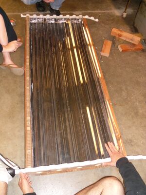
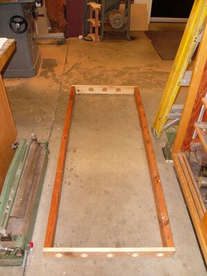
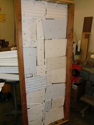
The Solar Collector, shown in Figure 3c is built using plywood and two by fours. The frame is shown in Figure 3d . The wood is fit together to create a rectangular box of 65" X 27", with plywood acting as a base. Then the box is insulated by fitting pieces of recycled Styrofoam together on the base, shown in Figure 3f . Next the copper metal sheet, acting as a heat conductor, is placed on top of the insulation. Lastly, the corrugated polycarbonate panel, acting as a glazing, is fit on top of the box using special corrugated end pieces and side pieces, and finally screwed down.
Materials Required[edit | edit source]
- Large piece of plywood
- Stainless steel screws
- Large sheet of copper(to the size of collector)
- Metal cutters
- 2' x 4' wood
- Insulation(recycled/reused common insulation)
- Food grade sealant with caulking gun
- Power drill including a circular drill bit
- Large piece of polycarbonate 65" x 30" at minimum
- Recycled window screen
- Thumb tacks
- Exterior flat Black spray paint
- 4' x 4' wood posts
Procedure[edit | edit source]
- Cut plywood to 65"x 27". This will be the base of the collector.
- Cut two pieces of 2 x 4 to 65" in length. Then cut two more pieces of 2 x 4 to 23" inches in length. The four pieces of 2 x4 will be the sides of the collector.
- Drill four two-inch holes, evenly spaced apart into one of the 27" piece of 2 x 4. This piece will be located at the front of collector where air will enter.
- Drill three two-inch holes evenly spaced into the other 27" piece of 2 x 4. This piece will be located at the back of the collector where heated air will pass into the heating cabinet.
- Cut 4 x 4 to make two pieces 10". Then cut each 4 X 4 at a 45 degree angle so that the legs of the collector will be able to be flat on the ground when the collector is set against the cabinet. . These two pieces will be the front legs of the collector.
- Screw the two cut pieces of 4 x 4 onto the plywood at either end which will result in the front of the collector.
- Use a caulking gun with food grade sealer to line the whole perimeter of the plywood before screwing the 2 x 4 pieces to ensure better insulation.
- Screw 2 x 4 pieces onto plywood, making sure to screw the 2 x 4 with 4 holes on the side with the legs. Then secure by screwing 2 x 4 together at the ends. This will now be the foundation of your collector.
- Lay down a layer of Styrofoam (from coolers or tv boxes) to cover the base surface of the plywood. Tack down the Styrofoam into the wood so that it does not move. Next lay down insulation on top of the Styrofoam, covering the whole area inside the foundation. A blanket, wood chips, or other insulating material can be substituted for the Styrofoam and insulation.
- Spray paint the sheet of copper with black paint. The black paint will help absorb as much heat as possible.
- Once paint is dry, fit the copper into the foundation on top of the insulation. Then cover the 2 interior sides of the 2 x 4 with insulation.
- Cut a rectangular piece of screen to fit the width and height of the 4 holes of the front 2 x 4. Staple the screen onto the inside of the 2 X 4. This will prevent insects from entering the collector.
- Caulk food grade sealant on the outer perimeter of the 2 x 4 to ensure glazing will be sealed tightly onto foundation.
- Lay 63" x 27" Glazing on top of collector foundation. Next screw the glazing onto the 2 x 4 to finish the construction of the solar collector.
Drying Cabinet[edit | edit source]
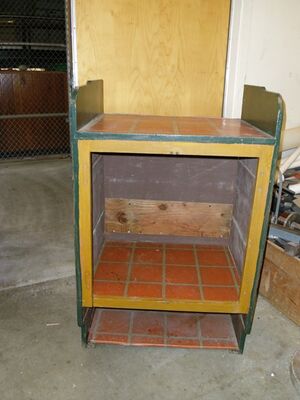
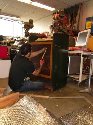
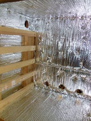
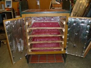
The drying cabinet, shown in Figure 3, the Sodhoppers used was actually a recycled cupboard. Any sort of box would have been a good candidate for the body of the dryer. The doors were removed and insulation was stapled to the inside of the cabinet, shown in Figure 3a. Next the shelving was put in. It consisted of 4 blocks of wood standing at each corner and smaller pieces of wood branching off of them to form a shelf that the drying racks could easily sit on, shown in Figure 3b. The Drying box with racks inside is shown in Figure 3j. Then the doors were put back on with new hinges and a latch to secure the doors, shown in Figure 3k.

Materials Required[edit | edit source]
- Plywood
- 2' x 4' lumber
- Staple Gun
- Insulation material
- Screws
- Recycled kitchen cabinet
- 1 x 1 lumber
- Drill with a circular drill bit included
- White water based paint
- Sand paper
- Extra polycarbonate glazing
- 1 x 2 lumber
- ¾ inch plywood
Procedure[edit | edit source]
- Remove the doors by unscrewing hinges. Leave cabinet doors off to the side.
- Drill two holes with a diameter of two inches into each side near the very top on the side near cabinet opening. This will be where the moisture from the drying food will escape.
- Drill three holes with a diameter of two inches into the back of the cabinet at the very bottom. This is where the collector will be connected and passing heat through.
- Staple insulation inside the cabinet covering every surface area. Make sure to cut out holes to fit the holes already drilled into the cabinet.
- Cut four pieces of 2 x 4 to fit the height of inside the cabinet. Drill screws into the 2 x 4 pieces connecting each to the four corners of the cabinet. This will be the foundation for the tray racks to be mounted on.
- Cut ten pieces of 1x1 lumbers to 15 lengths that will be drilled onto the 2 x 4 in the cabinet. Drill a screw into the 1X1 pieces connecting them horizontally to the 2X4 pieces that were previously drilled. Separate by six inches to make 5 mounts on each side. These mounts are where the drying racks will slide into.
- Now staple insulation onto the cabinet doors but do not screw them in yet.
- Screw two pieces of 1 x 2 lumbers on top of cabinet, one against each outer side.
- Make sure the cabinet has no oil based paint, if it does make sure to sand away all paint. Then paint the cabinet with two coats of paint. Make sure to allow the first coat to dry before applying second coat. Next paint the cabinet doors as you are painting the cabinet.
- Once the paint is finished drying completely, screw back in the cabinet doors.
- Next use the extra glazing piece from the collector and screw into the 1 x 2 pieces of lumber on top of the cabinet. Make sure the glazing is covering the cabinet horizontally. This will be the roofing of the cabinet to protect the hinges from rain and rusting damage.
- Cut two pieces of ¾" plywood to six inches in length and 3 inches in height to cover the top ventilation holes on the sides of the cabinet. These will be used for ventilation regulation by sliding back and forth to allow more or less air flow out of the cabinet.
- Cut 8 pieces of ¾" plywood to 2" x 7". These pieces will be the frame for the ventilation regulation.
- Place the sliding piece centered over the cabinet outtake hole leveled with the ground and make eighth of an inch markings below and above the piece of wood.
- Place one of the frame pieces directly below the bottom line made by the intake hole and another frame piece directly above the other line.
- Place two other pieces of wood on top of and to the outside edge of the pieces just laid down.
- Drill four screws into each corner of the frame in order to secure the frame.
- Repeat the frame building process with the other cabinet ventilation outtake hole.
- Cut 2 x 4 to 22 inches, then using a table saw cut a 45 degree angle section off the wood. This piece will be for the collector to mount on. Next screw the piece of wood with the shaved side facing up against into the cabinet below the 3 holes.
Base[edit | edit source]
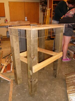
The Base, shown in Figure 3i, was constructed from four 4 X4's, plywood, and plexiglass. The plywood was set on top of the 4X4's and the plexiglass was mounted on each side to prevent the drying cabinet from moving.
Materials Required[edit | edit source]
- 4 x 4 wood
- Plywood
- Acrylic glass( 1 x 4 lumber can be used as a substitute as it is easier to cut)
- Screws
- Screw driver
Procedure[edit | edit source]
- Cut four pieces of 4 x 4 to 36" in length. These will be the legs for the base.
- Cut plywood to 27" x 18". The cabinet will rest on this plywood.
- Cut 4 pieces of acrylic glass. 2 pieces will be 27" x 6 "and the other two will be 18" x 6".
- Screw plywood onto the four 4 x 4 pieces so that the base can stand freely. Next screw the pieces of acrylic glass onto the sides of the base so that the cabinet will be safely fastened into the base. Make sure two or three inches of acrylic glass are above the base of the plywood.
Drying Racks[edit | edit source]
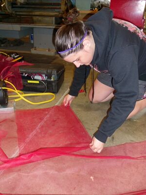
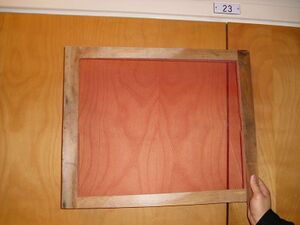
The Drying Racks are constructed from strips of plywood and nylon mesh, shown in Figure 3g. The mesh was placed in between a plywood base and top. It was stapled to the base and then the top was screwed down effectively holding the mesh down to create an air-movement-friendly drying rack. The finished product is seen in Figure 3h.
Materials Required[edit | edit source]
- 3 yards of nylon mesh
- Plywood
- Screws
- Staple gun and staples
Procedure[edit | edit source]
- To make five racks for the dehydrator, cut 10 pieces of plywood of widths of 2" and lengths to fit the cabinet space. Then cut 10 pieces of plywood 1" less than the width of the cabinet space they will be placed in and with widths of 2".
- Cut 10 pieces of plywood 4" greater than the width of the longest piece cut in the last step.
- Cut 10 pieces of plywood with widths of 2" and lengths 4" less than the width of the shortest piece cut in the first step in making the drying racks. Please note these lengths are extremely variable due to the different types of cabinets being available.
- Place the two longest pieces made in the first step in building the drying racks parallel to each other.
- Take the two other pieces from the first step in making the drying racks and place them on the ends of the parallel pieces.
- Separate the parallel pieces until a frame is formed.
- Take a staple gun and staple the attachment points of the frame to keep it in place.
- Take nylon mesh and cut it to the dimensions of the frame that was just built.
- Staple one side of the nylon mesh to a side of the frame containing one of the original parallel pieces.
- Take one of the pieces of wood cut from the second bullet in the drying rack steps and screw it down to the side containing the stapled down nylon mesh with two screws on each corner and two other screws spaced at equal distances from each other.
- Stretch the nylon to the other side of the frame and staple it down.
- Take one of the other pieces of wood cut from the second bullet and screw this down to the frame in the same manner as the one before.
- While stretching the nylon mesh over the other sides of the frame, staple down the mesh to the rest of the frame.
- Take one of the pieces of wood cut from the third bulleted step and screw it down to the frame to secure the mesh on the other part of the structure in a similar fashion as before then do the same with the other side.
- Cut of the excess nylon mesh from the drying rack.
- Repeat the process for the rest of the racks.
Putting it Together[edit | edit source]
Materials Required[edit | edit source]
- Screws
- 2 feet of aluminum ducting
- Screwdriver
- Wire cutters (to cut aluminum ducting)
- Aluminum Tape
Procedure[edit | edit source]
- Lift cabinet and place on top of base. Make sure it is completely flat on the base and fits snugly. Next screw the bottom of the cabinet onto the base to ensure stability.
- Stand collector up and lean against the back of the cabinet below the holes onto the 2 x 4. The legs should rest flat on the ground as well as the collector being at a 30-45 degree angle. Once the collector is placed in its final position, screw the edges of the collector into the 2 x 4.
- Once the cabinet and collector are both stabilized and connected to one another, it is time to connect the aluminum ducting. Cut the 2 feet of ducting into three pieces.
- Once 3 pieces are obtained, start by making sure the hole on the outside is completely covered by the ducting. Once covered, begin taping the outer edges with aluminum tape to seal completely ensuring no air escapes. After the hole is completely covered and sealed by the ducting, connect the other end of the ducting to the cabinet hole. Again make sure the ducting completely covers the hole and seal with the aluminum tape.
- Repeat the previous step 2 more times so that the 3 holes of the collector are connected to the 3 holes of the cabinet.
Gallery[edit | edit source]
-
Fig 3e: Justin Thompson attaching base to Solar Collector.
-
Fig 3l: Finished Dryer Box including Base.
-
Fig3m: Justin Thompson and James Courtney visiting with Laurel Tree Learning Center
Thank You[edit | edit source]
The SodHoppers would like to formally thank Marty Reed for all of his guidance and direction while building the design.


