
Gynecologic Simulator

The Sexual and Reproductive Health and Rights (STARS) - Cervical Cancer Screening and Treatment module's Gynecologic Simulator allows nurses, midwives, clinical officers, and medical officers to become confident and competent in performing visual inspection with acetic acid (VIA), and thermal ablation of cervical pre-cancer lesions as part of cervical cancer screening and treatment procedures performed in primary health care facilities and mobile units in resource-constrained settings. The Gynecologic Simulator contains 5 components: (1) base, (2) support pillars, (3) angled plane with triangular supports, (4) vaginal canal with augmented feedback, and (5) cervix models.
Gynecologic Simulator
[edit | edit source]Components
[edit | edit source]This section explains how to construct the 5 components of the Gynecologic Simulator.
The Gynecologic Simulator is designed with removeable cervixes so the learner can practice visual inspection with acetic acid (VIA), and thermal ablation of nulliparous and parous cervixes.
The Gynecologic Simulator is designed with a vaginal canal with augmented feedback for thermal ablation training.
The Gynecologic Simulator also contains a: (1) base, (2) support pillars, and (3) angled plane with triangular supports.
Cervix Dimensions and Appearance
[edit | edit source]The cervixes are designed to simulate the appearance of the os of nulliparous and parous cervixes.[1] The simulated cervixes also match the published dimensions on cervical width and length for nulliparous and primiparous women.[2]
The average cervix width for nulliparous women is 25.51 mm and average cervix length for nulliparous women is 29.18 mm.[2] The average cervix width for primiparous women is 28.18 mm and average cervix length for primiparous women is 31.89 mm.[2]
The nulliparous and parous cervix models can have acetowhite lesions added to simulate a VIA positive cervix.
The features of VIA positive acetowhite lesions are:[3]
- Distinct, opaque acetowhite area
- Margins should be well-defined, may or may not be raised
- Abnormality close to the squamocolumnar junction in the transitional zone and not far away from the os
Vaginal Dimensions
[edit | edit source]The upper range of linear vaginal length is 95.0 mm (9.5 cm) from the introitus to the cervix.[4] The Pederson medium vaginal speculum is 10.0 cm in length, and is an acceptable fit for many patients.
The diameter of the opening of a disposable pelvic speculum commonly used in an Ugandan hospital was measured by the Team Lead as 4.5 cm. The diameter of the opening of a medium sized Pederson vaginal speculum[5] is 6.0 cm at the handle and 3.0 cm at the ends of the speculum blades, which averages to 4.5 cm.
The vaginal canal is designed to be 4.5 cm in diameter, 14.0 cm in circumference, and 13.0 cm long (10.0 cm + 3.0 cm) to account for the vaginal length[4] and cervix length.[2]
Materials
[edit | edit source]- Cardboard
- Ruler
- Pencil
- 4 Tongue Depressors
- Scissors
- Knife or Blade
- Tape
- Paper
- Aluminum Foil
- Marker
- Pink Clay (2 ounces)
- White Clay
- Red Clay
- Jhpiego Flashcards
Gynecologic Simulator
[edit | edit source]Assembly Instructions
[edit | edit source]You will need the following materials:
- Cardboard
- Ruler
- Pencil
- Scissors
- Knife or Blade
- Tape
- 4 Tongue Depressors

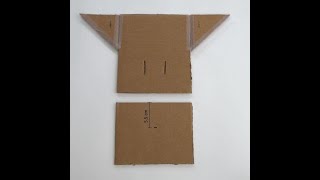
- Use scissors to cut out the base which is 19.0 cm long and 16.5 cm wide.
- Use knife to create two 5.0 cm long central slots 4.5 cm apart, 6.0 cm from each side, and 3.0 cm from the bottom.

- Use scissors to cut out the angled plane which is 13.0 cm high and 16.5 cm wide.
- Use knife tip to create one 0.5 cm wide, central horizontal slit 5.5 cm from the bottom.

- Use scissors to cut out two triangular supports which are 9.0 cm high and 9.0 cm wide.
- Use knife to create one 1.5 cm wide, central horizontal slot in each triangular support, 1.5 cm from the side and 2.0 cm from the bottom.

- Use scissors to cut out one tongue depressor in half.
- Use scissors to cut second tongue depressor in half. Then cut one half piece length into a 0.5 cm high piece.
- Set aside two remaining tongue depressors for taping and use in triangular supports.

- Apply tape to two sides of each triangular support.
- Attach triangular supports to base as shown in the photo.

- Apply tape to the bottom edge of the angled plane as shown in the photo.

- Tape angled plane to base. Press tape of angled plane down firmly to base.
- Flip up the triangular supports to attach the angled plane to the triangular supports (as shown in the video below).

- Insert one tongue depressor into each slot while leaving a small length projecting out of each slot.
- Tape the two tongue depressors together in the middle.

- Insert the tongue depressor piece into the 0.5 cm slot of the angled plane.
- Check the tongue depressor piece is positioned underneath the two taped tongue depressors behind the angled plane.

- Use scissors to cut out two rectangles 13.0 cm long and 3.0 cm wide.
- Use scissors to cut the tops of the rectangles at an angle.
- Use knife to create two vertical slots 1.5 cm wide in each support pillar. The lower slot should be 2.5 cm from the bottom and the upper slot should be 7.5 cm from the bottom of the support pillar.

- Insert one support pillar in each slot of the base.
- Insert a half tongue depressor horizontally into the lower vertical slots of the two support pillars.
- Insert a half tongue depressor horizontally into the upper vertical slots of the two support pillars.
Vaginal Canal
[edit | edit source]Materials
[edit | edit source]
You will need the following materials:
- Paper
- Ruler
- Marker
- Scissors
- Tape
- Aluminum Foil
Assembly Instructions
[edit | edit source]This section explains how to construct the Vaginal Canal of the Gynecologic Simulator. The Vaginal Canal provides augmented feedback to alert the learner if the heated Thermocoagulator Simulator probe shaft comes into contact with the vaginal sidewalls, and thereby, exposes the patient to a potential thermal injury.

- Mark out a rectangle that is 13.0 cm high and 14.0 cm wide.
- Extend the rectangle with a diagonal line out to the edge on the unused part of the paper. This will help you line up the ends of the cylinder so the diameter is 4.5 cm.
- Mark out an area that is 3.0 cm from the top edge of the rectangle. This area will not be lined with aluminum foil.
- Cut out the 5-sided polygon.

- Mark out an area of aluminum foil that is 1.0 cm out from the paper edge of the Vaginal Canal.
- TIP: On the aluminum foil, mark out the line up against the paper edge of the Vaginal Canal also. This marking will be useful later on when you attach the aluminum foil to the Vaginal Canal.
- Cut out the aluminum foil rectangle which will be used to line the inside of the Vaginal Canal for the Augmented Feedback feature.

- Apply tape to the area of the Vaginal Canal that will be lined with aluminum foil (area below the dashed line) so the foil layer will lie flat inside the Vaginal Canal.
- IMPORTANT: One should avoid taping over the aluminum foil because this will insulate the conductive material and prevent the augmented feedback circuit from functioning.
- Press the aluminum foil over the taped area of the vaginal canal to attach the aluminum foil to the area below the dashed line on the vaginal canal.

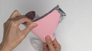
Flip the vaginal canal over and fold and press down the remaining 1 cm border of aluminum foil on the vaginal canal as shown in the image.

- Roll up the vaginal canal with the aluminum foil on the inside to form a cylinder of 4.5 cm diameter.
- Line up the two sides of the 13.0 cm lengths on the previously drawn rectangle to form a cylinder with a circumference of 14.0 cm.

- Apply a small amount of tape inside and outside the end of the cylinder that is not lined with aluminum foil to keep the top corners aligned. IMPORTANT: Tape should never cover the aluminum foil lining the inside of the cylinder.
- Carefully ensure the bottom edges of the cylinder remain aligned as you roll the remaining paper around the outside of the cylinder.

- Tape the outside end of the cylinder as shown. IMPORTANT: Be sure to leave a section of the folded aluminum foil exposed (untaped) where the alligator clip will be attached to allow the augmented feedback circuit to function.
- Use a ruler to check the diameter of the cylinder is 4.5 cm.
VIA Positive Cervix Models
[edit | edit source]Nulliparous Cervix
[edit | edit source]
You will need the following materials:
- Jhpiego Flash Card No. 49 (pages 133-134)
- Light Pink Clay
- Red Clay
- White Clay
- Pencil
- Ruler
The clay should be a water-based soft clay, like Play-Doh.
Not shown in image:
- Thermocoagulator Simulator - Augmented Feedback Circuit
- Gynecologic Simulator

Roll pink clay into a cylinder 2.5 cm in diameter and 3.0 cm long.

Press a pencil tip into the center of the pink clay cylinder to simulate the smooth, rounded os of the nulliparous cervix. TIP: Cover the pencil tip with cellophane to prevent the pencil from discoloring the clay cervix.

- Review the image of a VIA positive cervix on Flash Card No. 49 (pages 133-134) of the Jhpiego Flashcards and identify the squamocolumnar junction.
- The pink clay of the nulliparous cervix model simulates the squamous epithelium of the ectocervix.
- Add red clay to the cervix to simulate the columnar epithelium of the endocervix and define the squamocolumnar junction as a visible sharp border located near the external os.

- Review the image of a VIA positive cervix on Flash Card No. 49 (pages 133-134) of the Jhpiego Flashcards and identify well-defined acetowhite lesions that are adjacent to the squamocolumnar junction.
- Add white clay to the cervix next to the squamocolumnar junction to simulate clinically significant acetowhite lesions.

- Mount the VIA positive cervix model on the angled plane of the Gynecologic Simulator.
- IMPORTANT: Hold and stabilize the tongue depressor piece underneath the two taped tongue depressors behind the angled plane when mounting the cervix model on the angled plane.

- Place the Vaginal Canal over the VIA positive cervix model on the angled plane of the Gynecologic Simulator.
- IMPORTANT: Ensure the end of the Vaginal Canal that is not lined with the aluminum foil is adjacent to the cervix model because the clay of the cervix model can conduct the Augmented Feedback circuit.
- Place the aluminum foil-lined end of the Vaginal Canal between the two support pillars so the Vaginal Canal rests on the half tongue depressor in the upper slots.

- Tape the bottom underside of the base of the Gynecologic Simulator to stabilize it during simulation training.
- Connect the alligator clip (attached to the exposed wire of the red insulated end of the buzzer) of the Augmented Feedback Circuit to the exposed aluminum foil of the Vaginal Canal.
Parous Cervix
[edit | edit source]You will need the following materials:
- Jhpiego Flash Card No. 97 (pages 229-230)
- Light Pink Clay
- Red Clay
- White Clay
- Pencil
- Ruler
The clay should be a water-based soft clay, like Play-Doh.
Not shown in image:
- Thermocoagulator Simulator - Augmented Feedback Circuit
- Gynecologic Simulator

Roll clay into a cylinder 3.0 cm in diameter and 3.0 cm long.

Use the tip of the pencil to create the "fish mouth" appearance of the wider os of a parous cervix. TIP: Cover the pencil tip with cellophane to prevent the pencil from discoloring the clay cervix.

- Review the image of a VIA positive cervix on Flash Card No. 97 (pages 229-230) of the Jhpiego Flashcards and identify the squamocolumnar junction.
- The pink clay of the parous cervix model simulates the squamous epithelium of the ectocervix.
- Add red clay to the cervix to simulate the columnar epithelium of the endocervix and define the squamocolumnar junction as a visible sharp border located near the external os.

- Review the image of a VIA positive cervix on Flash Card No. 97 (pages 229-230) of the Jhpiego Flashcards and identify well-defined acetowhite lesions that are adjacent to the squamocolumnar junction.
- Add white clay to the cervix next to the squamocolumnar junction to simulate clinically significant acetowhite lesions.

- Mount the VIA positive cervix model on the angled plane of the Gynecologic Simulator.
- IMPORTANT: Hold and stabilize the tongue depressor piece underneath the two taped tongue depressors behind the angled plane when mounting the cervix model on the angled plane.

- Place the Vaginal Canal over the VIA positive cervix model on the angled plane of the Gynecologic Simulator.
- IMPORTANT: Ensure the end of the Vaginal Canal that is not lined with the aluminum foil is adjacent to the cervix model because the clay of the cervix model can conduct the Augmented Feedback Circuit.
- Place the aluminum foil-lined end of the Vaginal Canal between the two support pillars so the Vaginal Canal rests on the half tongue depressor in the upper slots.
- Tape the bottom underside of the base of the Gynecologic Simulator to stabilize it during simulation training.
- Connect the alligator clip (attached to the exposed wire of the red insulated end of the buzzer) of the Augmented Feedback Circuit to the exposed aluminum foil of the Vaginal Canal.
References
[edit | edit source]- ↑ International Agency for Research on Cancer. Atlas of Colposcopy: Principles and practice [Internet]. Colposcopy Digital Atlas. World Health Organization; 2021 [cited 2021 Nov 28]. Available from: https://screening.iarc.fr/atlascolpodetail.php?Index=13
- ↑ 2.0 2.1 2.2 2.3 Londero AP, Bertozzi S, Fruscalzo A, Driul L, Marchesoni D. Ultrasonographic assessment of cervix size and its correlation with female characteristics, pregnancy, BMI, and other anthropometric features. Arch Gynecol Obstet. 2011 Mar;283(3):545-50. doi: 10.1007/s00404-010-1377-5. Epub 2010 Feb 10. PMID: 20145939.
- ↑ Training of health staff in VIA, HPV detection test and cryotherapy - Facilitators' guide. New Delhi: World Health Organization, Regional Office for South-East Asia; 2017. Licence: CC-BY-NC-SA-3.0 IGO. The World Health Organization (WHO) is not responsible for the content or accuracy of any translation. The original English edition shall be the binding and authentic edition.
- ↑ 4.0 4.1 Bates CK, Carroll N, Potter J. The challenging pelvic examination. J Gen Intern Med. 2011 Jun;26(6):651-7. doi: 10.1007/s11606-010-1610-8. Epub 2011 Jan 12. PMID: 21225474; PMCID: PMC3101979.
- ↑ Pederson Vaginal Speculum Medium [Internet]. PEDERSON VAG. SPEC. MED | Medical Supplies & Equipment. Surgo Surgical Supply; [cited 2021 Nov 28]. Available from: https://www.surgo.com/pederson-specs-german/pederson-vaginal-speculum-medium--3.
| Authors | |
|---|---|
| License | CC-BY-SA-4.0 |
| Cite as | Medical Makers (2021–2025). "Gynecologic Simulator". Appropedia. Retrieved July 28, 2026. |