
Design and Optimization of Microstrip Antenna for Microwave Imaging of Breast Cancers

| Type | |
|---|---|
| Authors | |
| Status | |
| Years |
Abstract
This paper covers about detection of cancerous tumors in human breasts using a microstrip patch antenna which emits radiation in the microwave range. Fabrication of the patch antenna was done after analyzing simulation results of several patch antennas which were designed for different operating frequencies, using HFSS software. The cancer detection method mainly depends on the significant difference of electrical properties between a cancer tissue and a normal tissue. To validate the suitability of fabricated antenna to the purpose of detecting the breast cancers, two breast phantoms which have same electrical properties as an actual breast where only one phantom contains an artificial tumor, were prepared using different chemical recipes. Two patch antennas were used in the experimental set up for the purpose of transmitting and the receiving of the radiation. Final results of the system verified the validity of proposed method for breast cancer detection.
Understanding the market
[edit | edit source]Breast Cancer affects many women and has fatal conclusions if it does not cure perfectly. Early diagnosis of cancer greatly increases the chances for successful treatment and recovery. Around 50% of breast cancer cases end up with death, because the identification of the cancer is typically late. Even though there are some methods to detect breast cancers such as X –ray mammography, MRI and ultrasound those methods have some limitations and drawbacks.
Breast Cancer affects many women and has fatal conclusions if it does not cure perfectly. Early diagnosis of cancer greatly increases the chances for successful treatment and recovery. Around 50% of breast cancer cases end up with death, because the identification of the cancer is typically late.
Even though there are some methods to detect breast cancers such as X –ray mammography, MRI and ultrasound those methods have some limitations and drawbacks.
Limitations of current cancer detecting methods
[edit | edit source]- A slight risk of inducing cancer due to the ionizing radiation exposure. Frequent monitoring is difficult because of that.
- The risk associated with this dose appears to be greater among younger women.
- X-ray mammography has failed to detect up to 30% of cancers greater than 5mm in diameter due to its relatively poor soft tissue contrast.
Project goals
[edit | edit source]- Develop a device which can use frequently without causing any harm to the patient.
- Implementation of an accurate and sensitive device which can detect even smaller tumor cells.
Design
[edit | edit source]A. Antenna Geometry and Dimensions
[edit | edit source]-
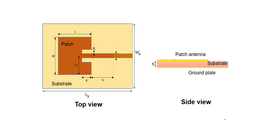 The Geometry of Microstrip Antenna
 -
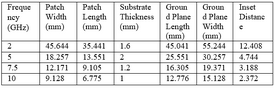 Dimensions of Simulated Antennas


Performance of the patch antennas differ from one to one based on their physical design and its feeding methods. There are single layer and multi-layer patch antennas which have one substrate material or several substrate materials between the conductive plates. In this project, single layer patch antenna type was selected. 4 patch antennas were designed for simulation at 4 different frequencies.
Costs
[edit | edit source]
Antenna Simulations
[edit | edit source]HFSS software is used to design and simulate above 4 microstrip antennas and their performance is simulated for comparison. Input impedance of the antenna was designed as 50Ω.
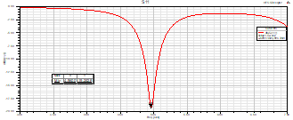
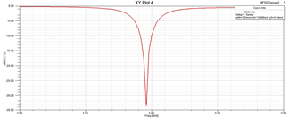
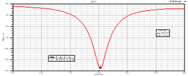
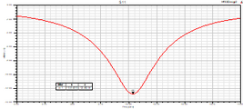
In these Simulations, the return loss and VSWR characteristics were obtained for the antennas to analyze the performance of antenna at each frequency. By analyzing these the optimum frequency was selected to fabricate the microstrip antenna. Return loss characteristics obtained for the 4 antennas are shown in the figures.
-
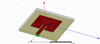 Simulated Antenna
 -
 329x329px
 -
 324x324px
 -
 351x351px
 -
 349x349px


For selecting the best frequency for fabricating the antenna minimum return loss vs antenna graph was plotted.
Table - Minimum Return loss analyzes of simulated antennas
| Frequency (GHz) | Return loss (dB) |
| 2 | -34 |
| 5 | -19.25 |
| 7.5 | -14.48 |
| 10 | -12.82 |
For a better performing antenna, the return loss should be minimum as possible. It is said a good antenna, if it has a return loss less than -15dB. Therefore, it was decided to select one antenna from 2GHz and 5 GHz antenna 2GHz antenna has the minimum return loss. And also, 2 GHz antenna is easy to fabricate because it has somewhat large dimensions than 5 GHz antenna. Considering all these facts, finally it was decided to select 2 GHz antenna as the best performing antenna to fabricate. Therefore 2GHz antenna was selected for further developments.
Simulations with Breast Models
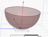
[edit | edit source]After determining the operating frequency, we modeled a 3D breast structure with the antenna and obtained plots of the current density distributions through simulations.
When a human body is exposed to external fields such as electric fields and magnetic fields, it induces fields and currents inside the body. When a patch antenna is kept in touch with the breast, same scenario happens. Therefore, a current density distribution plot of breast can be obtained. We obtained the following plots of current distribution using HFSS software.
-
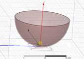 Simulated Breast Model with tumor
 -
 center
 -
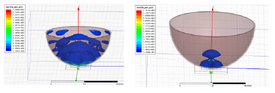 Current Density Distribution of Normal Breast vs Current Density Distribution of Breast With tumor


When a tumor is present, the current density in that area has increased according to the plot. The reason behind this phenomena is that the normal tissue and tumor tissue have different conductivity values. The tumor tissues have higher conductivity when compared with normal breast tissue so that tumor shows higher current distribution. This implies that a normal breast and a breast with a cancerous tumor can be accurately differentiated using this patch antenna. To detect the exact position of the tumor, different results should be taken, while changing the position of the antenna. To make that easier, an antenna array can be used.
Antenna fabrication and breast model preparation
[edit | edit source]Antenna Fabrication
Antenna was designed by Eagle CAD PCB design software. Some geometry values were too small hence a small error could change the operating frequency. To avoid this error PCB was fabricated by sending the design to china.
-
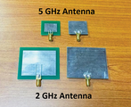 Fabricated Antennas
Antenna Parameter Measurement
The fabricated antennas are soldered to a subminiature A (SMA) connector and attached to a metal plug. To verify the antenna parameters, we used a calibrated Vector Network Analyzer (VNA). Return loss, smith chart and VSWR characteristics were obtained.
-
 Measured Return Loss

Table - Comparison of simulated and measured results
| Simulated | Measured | |
| Return Loss | -34 dB | -36.28 dB |
| VSWR | 1.04 | 1.033 |
' Breast Phantom Preparation
Two breast phantoms were prepared according to a chemical recipe [7] which have the same electrical properties as normal breast and a cancerous tumor. One phantom represents a normal breast and other one represents breast with cancer tumor. The different recipes are for the different tissue types presents in breasts. There are mainly two tissue types Low Water Content Tissue (LWCT) and High Water Content Tissue (HWCT). In here we have only created LWCT breast phantom with a tumor and without a tumor.
-
 reparation of Breast Phantoms

Experimental setup
[edit | edit source]To observe the final results of the system, experimental setup which consisted of a Synthesized Signal Generator and a spectrum analyzer was used. The Synthesized Signal Generator was used to generate a sinusoidal wave while Spectrum Analyzer was used to detect the receiving signal. The experimental setup is shown in the figure.
Both transmitting and receiving antenna were kept in contact with the surface of the breast phantom for accurate measurements and to avoid reflection by the breast phantom-air interface.
-
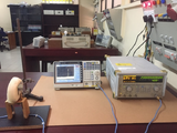 Experiment with breast phantoms

The transmitted signal was a sine wave of 2GHz which is shown as the figure 14. Input impedance of the designed antenna was 50 Ω. So that, a 50 Ω coaxial cable was used to connect both antennas with the spectrum analyzer and the signal generator.
-
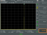 Transmitted Signal received by Spectrum Analyzer

Results and discussion
[edit | edit source]When analyzing the simulation results of the 4 antennas, it can be observed, that there is a difference between the actual resonance frequency and the designed operating frequency of the antenna. The reason behind this is the fringing field effect on the antennas. To reduce this difference, the width of the inset cut should be reduced. But this reduction causes the fringing effect to reduce which ultimately leads to reduction of radiation emitted by the antenna. So there should be a compromise between these two.
Below figures shows the received signal captured by the spectrum analyzer in the presence of normal breast phantom and in the presence of breast with tumor.
-
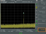 Received Signal in the presence of normal breast phantom
 -
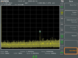 Received signal in the presence of the breast with tumor


Amplitude of the received signal when the breast phantom with the tumor is at the center of the two antennas was less than the amplitude of the received signal at the presence of normal breast phantom. A difference about 0.6 mV can be observed while analyzing above results. When nothing was present between the antennas, the received signal was around 26mV and this was reduced below 2mV when there was a breast phantom between them. The reason for this is the higher attenuation caused by the phantoms. For better accurate readings this experiment should be done in an antenna chamber in order to reduce background interferences.
Conclusion
[edit | edit source]When the simulation results and the measured results of the fabricated antenna are considered, they are approximately equal. The proposed antenna has very low return loss of -36 dB which validate its suitability to this application. For the whole range of frequency between 1-2.5 GHz, proposed antenna performs well. Above results shows that the difference between a normal breast and a breast with a tumor can be accurately identified using this antenna. Therefore, it can be concluded that the proposed antenna can be highly recommended for the application of breast cancer detection using microwave imaging.
References
[edit | edit source][1] Radouane Karli, Hassan Ammor, and Bal S. Virdee, "EARLY DETECTION OF BREAST TUMORS USING UWB MICROSTRIP ANTENNA IMAGING," London, Rabat, 2016.
[2] Sakshi Bohra, Tazeen Shaikh, "UWB Microstrip Patch Antenna for Breast Cancer Detection," International Journal of Advanced Research in Electronics and Communication Engineering (IJARECE), vol. 5, no. 1, p. 4, 2016.
[3] Rabia ÇalÕúkana, S. Sinan Gültekina, Dilek Uzera, Özgür Dündar, "A Microstrip Patch Antenna Design for Breast Cancer Detection," in World Conference on Technology, Innovation and Entrepreneurship, Konya, 2015.
[4] Y. Baskharoun, "Time Domain Approach to Microwave Imaging for Breast Cancer Detection," Ontario, 2010.
[5] Foster KR, Schwan HP, "Dielectric properties of tissues and biological materials: a critical review.," Pennsylvania, 1996.
[6] Ghaith Hattab, Mohamed El-Tarhuni, Moutaz Al-Ali, Tarek Joudeh, Nasser Qaddoumi, "An Underwater Wireless Sensor Network With Realistic Radio Frequency Path Loss Model," International Journal of Distributed, vol. 9, no. 3, p. 9, 2013.
[7] N. Mahalakshmi, A.Thenmozhi, "Design of Hexagon Shape Bow-tie Patch Antenna for Implantable Biomedical Applications," Alexandria Engineering Journal, p. 5, 2017.
[8] A. Trehan, "Numerical and Physical Models for Microwave Breast Imaging," Ontario, 2009.
[9] Amal Afyf, Fatima Riouch, A. ErrlChid, "A Novel Low Cost UWB Antenna For Early Breast Cancer Detection," Rabat, Lyon, 2015.
[10] M. Tarikul Islam, M. Samsuzzaman, M.T. Islam,M.N. Rahman, "A Compact Slotted Patch Antenna for Breast Tumor Detection," Kebangsaan, 2017.
[11] Yasir Ahmed, Yang Hao, Clive Parini, "A 31.5 GHz Patch Antenna Design for Medical Implants," International Journal of Antennas and Propagation, vol. 2008, p. 6, 2008.
[12] Y. Kuwahara, "Micowave Imaging for Early Breast Cancer Detection," in New Perspectives in Breast Imaging, Hamamatsu, 2017, p. 29.
[13] J.M.Sill, "Tissue Sensing Adaptive Radar For Breast Cancer Detection- Experimental Investigation of Simple Tumor Models," Calgary, 2005.
Contact details
[edit | edit source]Y.P.R.Kaveendra
ridmakaveendra7@gmail.com
| Authors | Ridma Kaveendra |
|---|---|
| License | CC-BY-SA-4.0 |
| Organizations | Department of Electrical Engineering Faculty of Engineering University of Moratuwa, Sri Lanka |
| Cite as | Ridma Kaveendra (2021–2024). "Design and Optimization of Microstrip Antenna for Microwave Imaging of Breast Cancers". Appropedia. Retrieved July 13, 2026. |