
Biocompostera/en

Composer for experimentation with biomaterials.
What is a biocompostress?
A biocomposter is a container of organic waste such as fruit shells, cuescos, biomaterials such as agar agar, organic waste in general. This to obtain a compost that is fertilizer produced from these degraded wastes in the wettest soil.
Why make a biocompostress?
In addition to using the organic waste that is generated day by day in our home, a totally free and chemical-free fertilizer fertilizer is manufactured, which can be used to nourish our plants.
Characteristics
This biocomposter has 3 accessories that allow complete composting in all its processes.
- Have a crusher made with 3D printing at the top that works with a crank that moves the crushers, which allow to break down the waste prior to pouring into the container, this stops decrease degradation time of organic waste being smaller pieces in size.
- Contains an aerator which is a tube with fins along it, located in the central part which by means of a crank rotates moving each layer of the compost to aerate them and improve the composting process.
- It has a door printed in 3D at the bottom to power remove composting from the last layer which is ready to be used as a subscription.
- Has a funnel at the bottom which serves to filter the liquid result containing all the optimal nutrients for the soil. It also has a humidity and temperature sensor to verify that the levels of these measurements are within the ideal composting parameters.
Material listing
| Name | Measurements | Units |
|---|---|---|
| Crusher | ||
| Nuts | 8mm | 6 units |
| Butts | 8mm | 6 units |
| 18mm | 8 units | |
| Screws | M4 x 30 | 6 units |
| M8 x 30 | 8 units | |
| M10 x 30 | 3 units | |
| Bearings | 6006 | 4 units |
| Aluminum plate | 155 mm | 2 units |
| Stop | 3D printing | |
| Biela | ||
| Bearing | 608 | 1 unit |
| Bolt | M8 x 25 | 1 unit |
| Butts | 18mm | 2 units |
| Arm | CNC cut | |
| Handle | 3D printing | |
| Aerator | ||
| Bearing | 608 | 2 units |
| Screws | 4 x 10 | 4 units |
| 4 x 30 | 3 units | |
| Wood veneer | 270 mm | CNC cut |
| Aluminum tube | 16mm x 380mm | |
| Fins | 3D printing | |
| Connector | 3D printing | |
| Support | CNC cut | |


Moisture sensor and irrigation pump
Its purpose is to monitor temperature and humidity within the biocomposter and in turn maintain the humidity level of the compost by means of automated irrigation, this in consideration of the importance of the humidity level for the compost in its different stages.
- Humidity: 40 - 60%
- Temperature: 45 ° - 70 ° C
| Sensor | |
|---|---|
| Printed lid | 3D PLA |
| Moisture sensor | DTH 11 and DTH 22 |
| Water pump | 9v |
| Irrigation hose | 4 mm |
| Arduino | A unit |
| DuPont cables | |
| Retractable thermos | 2mm and 4mm |
| Screen | 16x8 |
| Battery | 9v |
| Printed Carcasa | 3D PLA |
| Exterior | |
|---|---|
| Cover | 3D printing |
| Holders | 3D printing, 4 units |
| Funnel | |
| Filter | |
| Transparent mica | 190 x 40mm |
| Epoxy glue | |
| Balde | 5 gallons, 2 units |
| Rubber molding | Channel in c / diameter bucket |
| Door | 3D printing |
| Base | CNC cut |


How to build our biocompostress?
(Uploaded by Marek Senický, Jun 7 2014) in [one] and print the files in 3D to assemble the pieces as shown in your video.
3D print the crank cap and stop, crank outlet cover, joints for 4x buckets, bottom cover, aerator fins, adapter and connector of the aerator tubes.
CNC cut the upper caps of the crusher, upper lid of the aerator, crank arm, aerator support and base of the biocomposter.
Screw the wooden cover with the crusher with the aluminum plate, assemble crank with the bearing and stops, assemble wooden legs with round bases.
Extract the base of the upper bucket and make a hole in the base of the lower bucket to place the funnel, place funnel and filter, make small holes in the upper bucket for ventilation, make a hole in the buckettop for the crank and place its lid, glue the rubber molding on the edge of the buckets.
Make a hole in the bottom bucket for the lid where the compost is removed, make holes in the bottom bucket to screw the aerator bracket, holes in the side to get interior vision.
(Support, bearing, 3D printed joint, tube, 3D printing connectors and cover).
Laying wooden base and finallyplace lid of the crusher or aerator.


More details
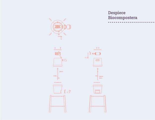 Despiece biocompostera
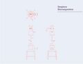 Despiece biocompostera
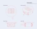 Trituradora
 Despiece trituradora
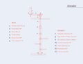 Aireador
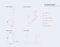 Despiece biela
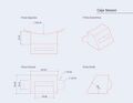 Caja sensor
 Despiece sensor
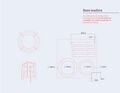 Base madera


