Bibliographic Information
Ueli Meier, Markus Eisenrinc, and Alex Arter. "The Segner Turbine: A low-cost Solution for Harnessing Water Power on a very Small Scale." (Swiss Center for Appropriate Technology) March 1983.
Go back to the AT Sourcebook.
This material is open.
NOTE: The date of original publication of this document is March 1983. As such, some information such as financial figures, may no longer be entirely correct.
Introduction[edit | edit source]
Nepal has a long tradition in utilizing water power in small mills. Traditionally, wooden vertical axis water wheels (Ghattas) are in use to provide motive power for numerous small grain mills. Although thousands of this type of water mill are still in use today, the scope of the future of these devices is limited because of the growing scarcity of timer and limited output power of these mills.
Initiatives undertaken by several local firms and individuals have resulted in the development of small water turbines during the past several years. Such turbines – mostly of the Cross-Flow type – are used in agro-processing mills with an output power ranging approximately from 7 kW to 15 kW. More recently, at present and in the future, these locally manufactured turbines are also installed for electricity generation with an output of up to 40 kW per unit. To date, more than 130 turbine units are in operation providing much needed power for milling and other purposes, and replacing many of the diesel engine-operated mills which become more and more uneconomical. It is thus evident, that water turbines are an attractive source of power.
Balaju Yantra Shala (BYS), a local engineering firm and mechanical workshop in Nepal, is engaged in the development and manufacture of water turbines in a pioneering role. Through contacts with numerous potential customers, and subsequent site surveys it became obvious, that, beside the many sites for turbine installations of 7 kW and higher output, there are also numerous sites which would have a lower generating potential. For these, installing a turbine of the existing type often turned out to be expensive. As a consequence, possibilities of developing a device for harvesting water power in the rance from 2 kW to a maximm of 10 kW were looked into. The result is the Segner Turbine described here. Making use of this turbine principle turned out to be especially suitable for mill operation, while offering considerable scope for cost reduction.
Brief history of the Segner Turbine[edit | edit source]

Applying the reaction principle of a jet of water to a rotating cylinder, J.A von SEGNER had herewith invented the Segner Wheel in the year 1750. He must have been inspired by D. BERNOULLI, who, in the year 1738, had theoretically deduced and experimentally confirmed the water-jet reaction effect. The Segner Wheel is by many authors the first turbine invented, although the term came into use only in 1825. It works purely n the reaction principal and so stands exactly opposite the modern Pelton Turbine which is a pure action turbine.
Some mills are said to have been operated by Segner Turbines in Germany shortly after its invention, and later, limited numbers were in use in the United States of America under the name BARKERS mill. Thereafter, the device was overtaken by other developments and was largely forgotten. Today, the Segner Turbine is applied for quite different purposes: lawn sprinklers and , with the use of compressed air, to run the propeller of helicopters.
Basic design and function[edit | edit source]
The Segner Turbine consists of an inlet channel (1) (refer to fig. 1) with a cylindrical funnel through which water enters a vertical pipe (2). At the bottom of this pipe, two (or more) radial pipes (3) are provided with bends to which nozzles (4) are fixed. This arrangement is done in such a way, that a water jet through these nozzles has an exactly tangential direction. The vertical pipe is held in place by a shaft (5) with spokes (6) which is supported by an upper and lower bearing (7), so that the vertical pipe with the radial arms at the bottom may freely rotate around its axis. A pulley (8) serves as the power take-off element.
The water consumption (Q) of the Segner Turbine depends on the head (H) under which the unit works, the total nozzle cross-sectional area and the circumferential speed of the nozzles. For a determined working condition, outflow through the nozzles is thus given. Inflow is then adjusted with the help of a simple sliding gate (9) in the inlet channel in such a way that the vertical pipe remains completely filled. The operator can easily find this out by watching the top of the inlet funnel: optimally the funnel should very slightly overflow and to achieve this, the sliding gate is adjusted accordingly.
The manufacturer may determine the appropriate rotational speed of the machine by choosing the nozzle pitch diameter (D). Since the machine is normally applied for heads ranging from 3 to 5 meters, in Nepal, BYS have standardized the nozzle pitch diameter at 1.5 meters. Operating speed (N) resulting from this is about 100 RPM (at a head of around 3 meters) and 150 RPM (at a head of 5 meters.) The required machine operating speed is achieved by choosing pulleys of appropriate diameters.
The nozzle diameter (d) defines the flow rate (Q) and is made smaller or larger to correspond to the actual flow available at the inlet. The machine works equally well with only one water jet. For a volume flow of 50% of the design flow rate, one nozzle may simply be capped a fact, which renders excellent dry season performance, when flow available is often drastically reduced. In this way, the Segner Turbine can be operated with a part load efficiency which is equal to full load efficiency. This, incidentally, is not possible with other turbines. Moreover, as will be show, the machine has also good self-regulating characteristics. This is a desirable virtue for operating milling machinery.
Operating characteristics[edit | edit source]

The study of the diagram (fig. 2) shows all the relevant characteristics of the Segner Turbine in operation. For better understand, an actual mill situation is explained with exact prediction of what occurs during load changes in the milling process. Performance characteristics at full design flow and at reduced flow may easily be found for optimal loading at the highest efficiency point, maximum power output, overloading of the machine and runaway conditions at no load. The operating points found for all these situations confirm, that the Segner Turbine indeed gives an excellent performance in a mill application.
The diagrams are valid for a machine with a maximum output (P) of 8 KW under a head of 4 meters, with a flow (Q) of 300 l/s.
Complete Technical data are:
Net head: Hn = 4m
Nozzle pitch diameter: D = 1.5m
Nozzle diameter: d = 0.113m
Nozzle coefficient: φ=0.96
Number of nozzles: z=2 (diagram a), z=1 (diagram b)
Flow Available: Q = 300 l/s (diagram a), Q = 150 l/s (diagram b)
For each of the two operating conditions, Q = 300 l/s and Q = 150 l/s, two diagrams are shown, the upper representing power output as a function of speed and the lower showing flow and efficiency as a function of speed. The lines i, ii and i+ii represent power consumption of the milling machinery installed:
i: A rice huller consuming 3KW at turbine optimum speed
ii: A flour mill consuming 4 KW at turbine optimum speed
i+ii: Both machines in operation 7 KW at turbine optimum speed
Diagram a): Flow (curve Q) amounts to 170 l/s with the turbine at a standstill, with the maximum torque available at this point. As the curve shows, flow then increases with speed (curve P) reaches its maximum. Since inflow is limited, Q does not increase further but remains constant. However, nozzle discharge under the full head increases due to the centrifugal forces if speed is increased further, which results in a drop of the water level (head) in the vertical pipe, until inflow and head related discharge are again in equilibrium, at the point of maximum (runaway) speed (191 RPM). This drop in head results in a steep drop of power output (P) between maximum – output speed and runaway speed. As we shall see, this peculiar characteristic comes in very handy for different loading conditions of the mill, without the need for inlet flow regulation.
Efficiency (curve η)of the turbine is highest at a speed of 128 RPM. This point is chosen for the design considerations for obvious reasons. In the diagram, this is represented by the vertical line of η max. With speed increasing further, efficiency at first decreases gradually up to the point of maximum power output, and then drops steeply to reach zero at runaway speed.
If now the load of the two processing machines i and ii is put on, operating speed will not be at maximum efficiency speed, but at the intersection of line i+ii with curve P, since operating characteristics have been selected for all occurring loading conditions. Any specific loading condition is therefore a compromise. In the case of the machines i+ii operating simultaneously, operating speed will be at 143 RPM and power consumption will amount to 7.7 KW. Thus available power is utilized efficiently, while the turbine efficiency is still above 70%.
In case of the need of operating either machine i or ii separately, processing output will go up against the rated figure, since the speed will be higher than rated, i.e. 181 RPM and 176 RPM respectively. Efficiency will drop drastically at these operating points to between 48 and 37% but this is irrelevant since here the generating potential is not fully utilized. The increase of speed in case of load dropping is limited: a factor of 1.05 when operating machine i only, up to a maximum of factor 1.46 when operating machines i+ii. This is considerable lower than a typical factor of 2 or even more in conventional water turbines. Operating safety and bearing life time are thus enhanced.
Diagram b): Here, the turbine is adapted to an inflow of 505 of full flow and nozzle discharge is cut to half simply by putting a cap on one of the nozzles. Note that no imbalance is caused by this since the capped radial arm remains full of water. Also, the efficiency (η) curve remains the same as with full flow. So do optimum speed and runaway speed, while the flow and power curves reach exactly 50% in magnitude as compared to the operation with two nozzles. Operating points for the processing machinery are different: it is more possible to operate the machines I and ii simultaneously, since insufficient power (4 KW) is available. Machine I (intersection of line I with the power curve) will operate at 167 RPM, and will consume 3.9 KW of the 4 KW theoretically available. For the operation of machine ii, insufficient power will be available at the maximum efficiency point. The turbine will adapt to this loading condition by lowering its speed to 101 RPM (the intersection of line ii with the power curve). At this point, power consumption will be reduced to 3.1 KW and the machine will consequently have somewhat lower than rated output. Increasing torque towards lower speed will guarantee trouble free operation also at this point, while on the other hand the factor for the runaway speed goes up to 1.9, relatively speaking.
Components of an installation[edit | edit source]
The basic components are the inlet channel (1), the Segner Turbine (2), a line shaft (3) with a number of pulleys of adequate diameter, and milling machinery (4), connected to the line shaft by means of flat belts. The line shaft in turn is connected to the turbine with another flat belt. A simple gliding gate (5) is utilized to regulate water inflow and excess water is discharged by the overflow (6) above the gate, while the water discharged by the turbine exits by the tail race canal (7). The inlet channel-turbine assembly is supported and held in place by a steel angle frame (8). The lower bearing of the turbine (9) is suitable to take axial loading and is held by a bearing block with splash-water protection, bolted to the foundation. A thrashrack (10) completes the installation.

Design details[edit | edit source]

Basically, the Segner Turbine is made from sheet metal of about 1.5 mm thickness. The square inlet channel is folded, welded and reinforced with angle iron braces. The vertical pipe of the turbine is rolled and welded longitudinally. Radial pipes were at first made from standard galvanized pipe bends, welded to the vertical pipe, and the second bend connected to the first with standard threaded sockets. In the recently standardized machine, these bends are replaced by manufactured pipe segments, while at the same time the number of radial arms with nozzles was reduced to two only, as compared to one of the first models with five arms. Although there is a present room for further improvements, the Segner Turbine of BYS has already been standardized, which reduces costs of the unit. Head under which the standardized machine is actually installed ranges from 1.5 to 5 meters and maximum flow permissible is 300 liters per second. It is thus possible to retain identical components for all installations except for the driven pulley, a section of the vertical pipe and the nozzles. Some further details are worth mentioning:
-
Figure 5: Mounting of nozzles
-
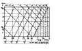
Figure 6: Discharge with different nozzle combinations
-
Figure 7: Application Diagram


- The vertical pipe with inlet funnel and the bottom with the radial arms are fabricated in 3 sections provided with flanges. Top and bottom sections remain unchanged for all applications, while the length of the middle section is varied to make up the total length which is equal to the head to be utilized.
- The shaft consists of two parts, the upper portion being welded to the top funnel with spokes and the lower end fixed in the same way to the bottom section of the turbine. Compared to a shaft which runs through the length of the entire pipe, considerable material is saved by this design.
- Nozzles are mounted on the radial pipes by means of flanges with bolts and nuts, as shown in fig. 5. The cross sectional area of the nozzle, its diameter, is subject to the water flow rate available at site. Nozzles are therefore made in variable sizes to suit the flow rate. The machine is delivered to the customer with a set of nozzles for design discharge and with an additional set of smaller nozzles to allow for reduced dry season flow. As stated earlier, one of the nozzles may be replaced by a blind flange, by that blocking water through one nozzle.
If the size of the smaller (spare) nozzles is chosen to make up 60% of the cross-sectional jet area of the larger nozzles, a number of configurations become possible, allowing for easy adaptation of the machine to flow patterns which may change throughout the year. It is noteworthy that for all flows adjusted with a combination of large nozzle/small nozzle/blind flange, the efficiency of the turbine remains as under full flow conditions. The table in fig. 9 shows what flow conditions can be met with the nozzles as described. The application diagrams (fig. 10) furthermore, shows the available shaft power with 2 sets of defined nozzle diameters.
-
Figure 6: Discharge with different nozzle combinations
-
Figure 7: Application Diagram
-
Figure 8: Top bearing
-
Figure 9: Bottom thrust bearing


- The bearings used in the Segner Turbine are of two kinds. At the top, a radial ball bearing of the flange type (as shown in fig. 8) is used, while at the bottom, a common taper roller bearing (fig. 9), with a special water protected housing is used. The entire weight of the machine is taken up by this thrust bearing. As an alternative, a taper bush bearing is also considered. Operating experience will have to show which type is preferable.
Overall main dimensions of the machine are in the following for an output range from 3 kW (at design flow) to 10 kW.

Costs and economic viability[edit | edit source]
At prices of early 1983, a complete Segner Turbine manufactured by BYS in Nepal, will cost no more than Rs 8’000 – (approx. U.S. $670.-) ex-works. This price may not be relevant for other countries but may serve here to arrive at an estimate of economic viability under specifically Nepalese conditions.
Other costs of a fully equipped Segner mill are highly site specific. It therefore seems the most realistic to use the average of costs of actually existing turbine mills and to consider differences in the installation of turbine mills and Segner Turbine mills. The following are the obvious differences of already existing turbine mills and of mills equipped with Segner Turbines:
- A Segner Turbine installation requires no penstock pipe and no forebay basin.
- This eliminates one cost item (penstock) completely and reduces another item (for cement) drastically.
- Because of smaller power output, smaller and/or fewer processing machines are installed, which also reduces power transmission costs.
- Developing smaller water power potentials generally costs less for survey, design and installation than larger potentials, usually, existing irrigation canals can be used.
The table in fig. 11 shows a fairly representative computation of costs for a Segner Turbine installation versus average costs of existing turbine mills.

A report by the Asian Development Bank * shows that on the average, investment costs for turbine mills are about Rs. 8’000.- per kW of power actually available. Turbine mills of this cost have proven more than 100 fold to be economically viable in Nepal. This indicates that a Segner Turbine installation with not less than 4 kW of power available throughout the year will also be economically viable. Looking at investment costs in terms of costs per unit power available, permits easy comparison of different devices and to illustrate this, it will be shown what the acceptable investment costs for a traditional mill would be for the same economies and in a given situation, i.e. a net head of 4 meters and a full flow of 200 liters per second during eight months of the year, and a reduced flow of 80 liters per second during the remainder of the year:
- Segner Turbine installation: output under full flow conditions = 5 kW and under reduced flow conditions = 2.2 kW, resulting in a weighted-average of over 4 kW available power. Acceptable investment costs = Rs. 32’000.—(as shown).
- Traditional water mill: The efficiency of a vertical axis wheel with open flume is over 3 times less than that for a Segner Turbine. Resulting output for wet and dry season is therefore 1.6 kW and 0.7 kW respectively. A weighted average of power available would consequently be 1.3 kW.
Such costs for a traditional mill are probably somewhat higher than actually occurring. It must therefore be realized that in the power output range of around 1 kW, applied for grain milling only, the local “Ghatta” remains the right solution. Where other uses of power are in demand on the other hand, such as for oil extraction and for rice dehulling, traditional technology will not do. There, with just the three-fold investment as compared to costs of a traditional mill, an economic solution is now possible for the first time by using a Segner Turbine.
Conclusions[edit | edit source]
The Segner Turbine is thus shown to be a suitable device for a limited application range. It neither replaces higher powered turbine installations nor lower output traditional water mills, but clearly fills a gap between these two. It also follow from this that within the application range of either the existing turbines or the traditional water mills, it would be wrong to invest in a Segner Turbine. More specific reasons for this are the following:
- The local “Ghatta” is a low power output device which has been technically adapted to its environment over a long period and which is economically optimal in the prevailing situation. Scaling down a Segner Turbine – or any other manufactured device – is not likely to attain such economies.
- Scaling up a Segner Turbine into the output range of locally manufactured turbines, on the other hand, has not economical but rather technical limitations: delivery of a relatively large flow of water into the vertical pipe of the Segner Turbine results in a loss of head, which may no longer be negligible. It must also be borne in mind, that the full weight of the vertical pipe including its water contents, must be taken up by the bottom thrust bearing, thus limiting the technical feasibility of increasing working head. And a last point: unlike conventional turbines the Segner Turbine requires vertical drop in the topography to utilize water head. It is obvious that the head developable is limited, depending on the situation at a specific site.
