
215 Emergency photovoltaic box

| Type | Photovoltaic system |
|---|---|
| Authors | Emily Handy Sol Jané Justin Romani |
| Location | Humboldt, United States |
| Status | Deployed |
| Years | |
| Made | Yes |
| Replicated | No |
| Uses | photovoltaics, energy generation |
The Emergency Photovoltaic Box, created for Appropedia, provides an affordable source of clean power during shelter-in-place emergencies where power is often lost. The project includes a collection of emergency preparedness resources as well. This project was designed and created by Elemental Solar, a team of students; Emily Handy, Justin Romani, and Sol Wright. These are students from the California Polytechnic University, Humboldt Spring 2022 section of the Engr205 Introduction to Design course.
Background
[edit | edit source]At the beginning of the semester, (January 2022), Appropedia presented multiple proposals for design projects that featured solar components. These were affordable, relatively simple to construct, open-source projects. Elemental Solar chose to design a solar system intended for use in the case of wildfires and subsequent rolling blackouts, earthquakes, or any other disaster situation where power might not be available. Some members of Elemental Solar have firsthand experience with these events, and are familiar with the problem at hand. Emilio Velis, the executive director of Appropedia worked with the team to guide our design process and provide feedback as the project was developed further.
Problem statement
[edit | edit source]The objective of this project is to design an open-source, solar powered system, using a reclaimed panel, that provides power during shelter-in-place emergency events and encourages emergency preparedness. Shown below is a table of the criteria we generated for our design, with weights from 1-10 that we determined during our design process.
| Criteria | Description | Weight (1-10) |
|---|---|---|
| Emergency Application | Able to power essential devices (phones, laptops, low-power medical equipment, etc.) during outages. Encourages emergency preparation (instructs gathering of information/materials) | 10 |
| Reproducibility | Must be able to be recreated by an individual or group with a similar level of skill. Design must use materials that are widely available in the intended area of California/United States. | 9 |
| Reliability | Requires minimal maintenance, less than 10 hours a year, to be kept in functional order in case of emergency. | 8 |
| Cost | Must be within $425 budget | 8 |
| Accessibility | Product must be able to be used by average members of a household (individuals 12-70) Design must use materials that are widely available in the intended area of California/United States. | 7 |
| Aesthetic Appeal | Product is enjoyable to look at. | 4 |
Prototyping
[edit | edit source]Most of the prototyping of the final design for the emergency photovoltaic box occurred while it was being designed and built. We did perform some preliminary prototyping prior to commencing construction and refinement of the final design. This "preliminary prototyping" was done by brainstorming multiple different solutions to our initial problem by drawing the suggested designs.
We created six alternative designs in total, but we chose to pursue building a design closest to what is shown in the image of the sketch on the right. This preliminary design is a solar panel on a collapsible frame, connected to a battery that is contained in a cubby box. This cubby box contains a charge controller and inverter, as well as the battery and another cubby for storage space.
-
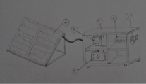 A drawing of the alternative solution that we chose to base our final design off of.

Final product
[edit | edit source]The final product consists of three major components: a modular and adjustable frame to hold a solar panel, an electrical box facilitating charging outlets, and an emergency preparedness box containing relevant instructions, information, and storage. Together, these three pieces constitute a system that provides relief during shelter-in-place emergencies.
-
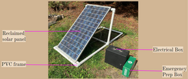 Labelled overview of the final design.

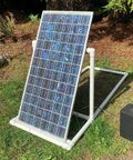
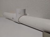
The first piece of the system is a frame for the solar panel. The frame is made from PVC. The vertical section of the frame is its key component. The section is removable for storage. The vertical section also slides back and forth along the horizontal base. Once the desired position is achieved, removable bolts hold the vertical section in place as seen in the image below.
-
 Removable bolts

This movement, shown in the images below, allows the frame to hold the solar panel at a variety of angles, allowing for optimal sunlight collection.
-
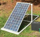 Angle 1 (≈36°)
 -
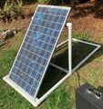 Angle 2 (≈45°)
 -
 Angle 3 (≈60°)


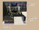
The second piece of the system is a battery box / charging station containing the primary electrical components of the project. The system, shown in the labelled image below, includes a charge controller, Lithium Iron Phosphate battery, inverter, and rechargeable household batteries. This system connects to the solar panel via a cable. The connection method will allow the solar panel to be set up outside, while the battery box with its less-durable components stay inside for protection and ease of use.
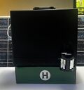
The final part of the system is a box containing instructions for the set-up, use, and maintenance of the first two components, as well as localized relevant emergency information. The box, depicted below, contains instructions for the use of the Emergency Solar Battery Box, printouts of emergency response procedures, an emergency contact template created by FEMA, a note with expected dates for maintenance, and any additional items desired by the user. We included a rechargeable battery system that plugs into the outlet in the electrical box. These additional items may include emergency medicine, water treatment tablets, extra batteries, and other such resources. The user may also wish to purchase a box that is more durable if they are expecting long periods of time in storage.
-
 An image of the electrical components box, with labels.
 -
 Survival information box


Construction
[edit | edit source]The construction of the system is broken down into three sections; building the frame, electrical set up, and preparing the storage box.
Building the Frame
[edit | edit source]Frame design is highly dependent on the dimensions of your reclaimed panel. Our panel is quite large, with dimensions of 4'5" by 2'3". Based on these dimensions, we created the design seen below. We want to create angles ranging from roughly 20º to 70º, and have quite a large base section for stability. With this in mind, we chose to make the frame 3' tall by 3' wide by 6' long. This height was later cut down to 2.5' to better fit our panel.

The PVC Pipe and Size Quantity below describes the lengths of PVC pipe that need to be cut before assembly. We chose to use 1 ½" pipe for extra stability, and to ensure holes could be drilled through the pipe with compromising integrity.
| PVC Pipe Size & Quantity | |
|---|---|
| Size | Quantity |
| 3' | 5 |
| 2.5' | 2 |
| 6' | 2 |
| TOTAL LENGTH: | 32' |
The following PVC connectors, see the table below, are also required to build the frame. These connectors are also 1 ½" to match the pipe size.
| PVC Connector Type & Quantity | |
|---|---|
| Type | Quantity |
| 3-Way Elbow | 2 |
| 90 Degree Elbow | 6 |
Once the PVC materials are assembled, follow these steps:
- Cut the back off and sand the interior of the 3-Way Elbows until the 1 ½" pipe can slide smoothly through one side. We used a Dremel Rotary Tool with a cutting wheel and sanding bits. A hole needs to be drilled through the side of the elbow the pipe slides through. The bolts go through these holes to hold the frame in position.
-
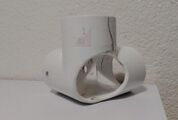 3-way PVC elbow
 -


- Put two 6' PVC lengths and one 3' PVC length together with two 90 Degree Elbows, creating 3 sides of a rectangle. This forms the base of the frame. A second 3' length of PVC needs to be cut down and epoxied to the first 3' length. This creates a channel for the edge of the panel to sit in. When finished, this should look something like the image below.
-
 Modular Frame Construction - Step 2

- Assemble the vertical section of the frame using the two 3-Way Elbows, two 90 Degree Elbows, two 3' lengths of PVC, and two 2.5' lengths of PVC. We also added some insulation foam to the top section to cushion the upper edge of the solar panel. Slide to vertical section of the frame onto the base. When finished, the frame should look something like the image below.
-
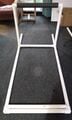 Modular Frame Construction - Step 3

- Drill holes through the 6' PVC lengths. These holes match the holes through the 3-Way Elbows and hold the bolts. Put the panel on the frame and find three desirable positions, then mark and drill the holes. The finished holes should look something like the image below.
-
 Modular Frame Construction - Step 4

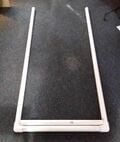
- Add the final side to the base with the last 3' PVC length and final two 90 Degree Elbows. Slide the vertical section into place and secure with bolts. The frame is finished, and should resemble the image below.
-
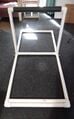 Modular Frame Construction - Step 5 (Finished)

Electrical Set Up
[edit | edit source]The following are instructions for wiring and assembling the electrical components. All instructions use the dimensions and specifications of the specific components of this project.
STEP 1: Test and Evaluate Reclaimed Panel
NOTE: This step is unnecessary if the builder is not using a reclaimed panel.
Using a reclaimed panel can be a major benefit in terms of cost and sustainability, but presents a greater challenge than using a new panel. The panel should be evaluated both to check that it works, and to evaluate its output potential.
To test our reclaimed panel, we brought the panel into direct sunlight and tested the outputs on the back with a multimeter. We determined that our panel had two sets of outputs. In the image below, the multimeter is testing one set of outputs on the left. There is a second set of outputs on the right. Each set of outputs generated around 20 Volts and 2.5 Amps.
-
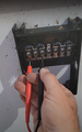 Multimeter testing reclaimed panel

The double outputs gave us the option to wire the panel either in series or in parallel. Wiring in series would result in a total output of around 40 Volts and 2.5 Amps, while wiring in parallel would output around 20 Volts and 5 Amps. Based on the specifications of the electrical components and the advice of Engineering 215 instructor Lonny Grafman, we decided to wire our panel in parallel. See the below image for the final wiring of our panel.
-
 Wiring on the back of the panel.

NOTE: Panel testing and evaluation is highly dependent on whatever reclaimed panel you are using. Our testing and evaluation are included as an example ONLY.
STEP 2: Wire the Panel
Connect wires to your panel as appropriate. Our wiring is shown in the image above for reference, but your wiring will likely be different. This wire should be long enough to run from your panel through a window to the other electrical components, so plan accordingly.
The wires should be encased in some sort of tube or conduit to protect them from the elements. We used vinyl tubing, see the image below, but a variety of materials could do the job.
-
 Output wires encase in vinyl tubing

The panel and other electrical components need to be able to detach from each other. Solder one side of a two-way DC plug to the end of the wires as shown below. The other side will attach to the charge controller in a later step.
-
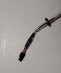 One side of two-way DC plug wired to panel

STEP 3: Wire the Battery & Fuse
Attach wires to the positive an negative leads of your battery. A fuse holder needs to be soldered to the positive side to protect the battery. After the fuse holder is connected, place a new fuse inside. Your wired battery and fuse should look similar to the image below.
-
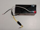 Wired battery & fuse

STEP 6: Connect the charge controller
The panel, battery, and inverter need to be connected to the charge controller in a specific order. If this is done incorrectly, this can damage the charge controller. Our charge controller uses the following connection order:
- Battery
- Solar Panel
- Inverter
Your charge controller will likely use the same order, but you should follow the instructions on your charge controller just in case.
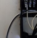
For our system, we first connected the battery. Then, we attached the other side of the two-way DC plug and connected it to the solar panel. Finally, we connected the inverter. To connect our inverter to the charge controller, we had to strip the wires and attach new leads. Your connection process may vary depending on your components, but yours should look similar to the below image when finished.
-
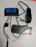 Electrical components wired to charge controller

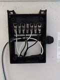
STEP 7: Set up Charge Controller
Your charge controller will likely need to set several parameters for your charge controller, such as float voltage, discharge stop and reconnect voltage, work mode and battery type. This will be highly dependent on your individual electrical components and charge controller. Check the specifications of your electrical components and follow the instructions on your charge controller.
-
 Assembled electrical box with lid off

STEP 8: Consolidate Electrical Components into Box
To keep all the electrical components both protected and together, they should be consolidated into a single box. While not strictly necessary, we designed a custom-fit box to hold our components and allow use while the box is closed. See the images below.
-
 Electrical component box with lid on

Emergency Preparedness Materials Storage Box
[edit | edit source]To build the emergency preparedness box, the user must first decide which situations to prepare for. Elemental Solar is based in Northern California so the example box is set up for wildfire and earthquake preparation. This will vary based on user location. After this is decided, the user should use the internet or the local library to research updated emergency procedures for the desired emergency event. FEMA is a good resource for this. For English speaking users, we have printed FEMA's "Family Emergency Communication Plan" template[1] to fill out with phone numbers the user would like to have available during a shelter-in-place emergency event. After the procedural materials have been printed, (some may wish to laminate/protect these as well), the remaining space should be used for resources. Emergency medication, non-perishable foods (canned beans, grains, dried fruits/meat), and items like extra batteries, flashlights, and candles are recommended. It is also recommended to make note of expiration dates on food items, and periodically (at least once a year recommended) update emergency procedures and contact information.
- ---[1] Contact template. Family Emergency Communication Plan, FEMA, 2017, https://www.caloes.ca.gov/ICESite/Documents/family-communication-plan_fillable-card.pdf
Bill of materials
[edit | edit source]This section presents the total cost of our design. These items are what we used and propose using in a system with similar specifications. Note that we used a reclaimed solar panel in our design, which greatly reduced our costs, and we suggest that you try to do the same. Reclaimed panels can be free, or sold at a reduced cost, depending on the source. Depending on the specifications of your panel, you will have to adjust the rest of the components. We also chose to repurpose two used boxes for both our electrical box and emergency preparedness box.
| ITEM | COST |
| LiFePO4 Battery | $49.99 |
| Charge Controller | $14.99 |
| Inverter | $17.98 |
| Rechargeable Battery Kit | $14.49 |
| Reclaimed Solar Panel | $0.00 |
| Dremel Cut-Off Wheel | $7.59 |
| Dremel Sand Drum | $5.69 |
| PVC Pipe (30') | $35.07 |
| PVC Elbow (2) | $5.38 |
| PVC Cement/Primer | $11.69 |
| PVC Elbow (4) | $10.76 |
| PVC Outlet (2) | $10.78 |
| Hardware | $15.40 |
| Pipe Insulation (3') | $6.29 |
| PVC Pipe (3') | $4.38 |
| Wire Connectors | $5.60 |
| Hardware | $0.60 |
| Vinyl Tubing | $5.30 |
| Epoxy (2) | $13.58 |
| 14 Gauge Wire (2) | $22.88 |
| 2-Way DC Connector | $2.39 |
| Fuse Holder | $3.99 |
| Fuses | $3.09 |
| Slide Terminal | $6.69 |
| Acrylic Sheet | $12.74 |
| Plastic Cutter | $7.30 |
| Heat Shrink | $7.80 |
| Sandpaper | $2.54 |
| File | $7.59 |
| Repurposed Box (2) | $0.00 |
| TOTAL | $312.57 |
Operation
[edit | edit source]How to operate the Emergency Photovoltaic Box once all parts are assembled and ready for use:
- Set up the modular frame outside
- Place solar panel on frame and adjust frame to desired position for maximum sunlight collection.
- Run cable from solar panel through window or door into house.
- Ensure battery is connected to charge controller.
- Connect panel cable to electrical box with two-way DC plug.
- Ensure inverter is plugged in.
- Plug smaller devices (e.g. laptops and/or phones) into inverter outlets.
Maintenance
[edit | edit source]The battery will require charging every six months according to the battery specifications. These specifications also recommend storing the battery at at least 75% charge. Charging will take about 4 hours if you charge the battery with the solar panel deployed in direct sunlight. During charging, emergency preparedness resources should be reviewed and updated, if necessary. Updating emergency information should take about half an hour.
Maintenance schedule
[edit | edit source]- Every six months:
- Charge battery if it has not been used
- Check emergency procedures and update contact information,
- Replace expired food and medication
- Replace the panel and battery as needed. Depending on how old the panel is, that could be in just years or decades. The battery has a lifespan of upwards of 10 years if used for 1 full cycle everyday, so provided this system is only used in emergency situations, it would last decades as well[1].
Conclusion
[edit | edit source]Testing results
[edit | edit source]We ran a load test to measure time, energy used, and battery loss. Battery loss was monitored visually on the charge controller interface. The system was set up outside on a clear, sunny day. The battery, panel, and inverter were all connected to the charge controller as per the building and operation instructions. An electricity monitor was plugged into the inverter to monitor the system output. The electricity monitor was used to record time as well as a running total of energy used in kilowatt hours.
The load test measured time, energy used, and battery loss. Battery loss was monitored visually on the charge controller interface.
| Load Test | |||
|---|---|---|---|
| Time (hours) | Devices | Energy Used (kilowatt hours) | Battery Loss (%) |
| 0.5 | 1 laptop and 1 cell phone | 0.02 | 0 |
| 1 | 1 laptop and 2 cell phones | 0.04 | 0 |
| 1.5 | 2 laptops and 2 cell phones | 0.06 | 0 |
For the discharge test, which monitored time and energy used, the system was set up inside with the panel covered. Again, the electricity monitor was plugged into the inverter. However, this time only a single laptop was plugged into the electricity monitor. The laptop was uncharged and running multiple, CPU-heavy programs to ensure an accurate energy draw.
| Discharge Test | |
|---|---|
| Time (hours) | Energy Used (Watt hours) |
| 3.8 | 80.0 |
Discussion
[edit | edit source]Load Test
[edit | edit source]The results of the test indicate that the max tested load of two laptops and two cell phones can be run indefinitely while the panel is in use, assuming that weather conditions mirror the conditions during testing. No battery loss was observed during the load test, meaning that the panel was able to charge the battery at a faster rate than the devices were drawing power.
Discharge Test
[edit | edit source]Given that the LiFePO4 battery is rated at 128 Watt hours, a full discharge of 80 Watt hours may seem low. However, two factors need to be taken into account.
- Inverter inefficiency: Depending on the product, the inverter may have a relatively love efficiency, which will effect the battery discharge.
- Discharge stop: The charge controller prevents the battery from being fully discharged. This protects the battery and increases its lifespan. The discharge stop setting for this project cuts off discharge at around 30% battery.

With the above considerations and some simple calculations, the energy use of the discharge test seems much more reasonable.
Lessons learned
[edit | edit source]Some lessons that we learned during the process:
- Make sure to understand your panel before soldering your wires. Old solar panels like ours will not always have the +/- labeled, so test which output is which with the wires attached to the charge controller (and the battery!)
Next steps
[edit | edit source]Here are some suggestions for further developing this design.
- Explore using more panels and a larger battery, sizing the rest of the system to power larger devices.
- Explore a system that doesn't require a battery.
- Explore permanent installations.
Troubleshooting
[edit | edit source]These are hypothetical issues that might arise while using the Emergency PV Box.
| Problem | Suggestion |
|---|---|
| Devices not charging | Make sure that the charge controller is running electricity to the devices by pressing the far right button, which will make a bulb appear or disappear on the right of the display. If the bulb is there, the devices should charge. If the bulb is not there, electricity is not running to the loads and devices will not charge. If that does not work, make sure that the solar panel is wired correctly and all of the wires are soldered properly. |
| Frame leans too much | Reinforce PVC with whatever can be used. |
Team
[edit | edit source]References
[edit | edit source]- ↑ Avada Classic. 2021. How long will a lithium iron phosphate battery last? - nRuiT. [online] Available at: <https://www.nruitpower.com/news/how-long-will-a-lithium-iron-phosphate-battery-last/> [Accessed 5 May 2022].
| Authors | Emily Handy, Sol Jané, Justin Romani |
|---|---|
| License | CC-BY-SA-4.0 |
| Organizations | Cal Poly Humboldt |
| Cite as | Emily Handy, Sol Jané, Justin Romani (2022–2026). "215 Emergency photovoltaic box". Appropedia. Retrieved July 21, 2026. |