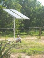
UTC in Mexico built a Solar Learning Station with help and instruction from Lonny. We have constructed a local version of the learning station to be used to instruct students, faculty, and visitors. By building a station here, we achieved the dual purpose of helping people learn about PV and we learn some hands-on, in-depth knowledge of PV systems.
Description of Goals and Purpose[edit | edit source]
The goal of the project was to improve upon UTC's system and produce a functional, convenient, portable, and instructional learning station. By meeting the criterion mentioned below, we hope to stimulate and foster interest in PV systems with students, faculty, and visitors. This station will be used by HSU students, faculty and the community as a hands-on demonstration of photovoltaics. We are trying to improve on the project created by UTC Solar Learning Station by learning from their process and adding as much as we can to it. The station will be at HSU. We hope it will lessen any fear of the unknown and create interest in the use of PV technology in as many locations as possible. We have created an even more durable, educational and user-friendly model than was created by the folks at UTC by building on the knowledge and functionality they have provided.
Literature Review[edit | edit source]
There has been substantial discussion and writing on PV design, installation and maintenance. Because this is meant to create and foster interest in PV by people that may or may not have had any experience in this area, we have provided an overview of the historical literature on PV as it applies to our project. literature review.
Criteria[edit | edit source]
| Criteria | Constraint | Success? |
|---|---|---|
| Cost | Under $400 | Yes |
| Appropriateness of materials | Majority of materials obtained locally (100 miles), used or donated | Yes |
| Adaptability | Easily replaceable, interchangeable, plug and play, parts | Yes |
| Portability | Movable by two people and fits in a car | Yes |
| Easily duplicated/documentation | Easy to re-create by others and clearly documented | Yes |
| Maintainability | Easy to maintain by trained staff and clearly documented | Yes |
| Ease of comprehension | First time user can use | Yes |
| Safe | Least chance of electric shock and Clear instructions | Yes |
| Durability | Must weather the constant use and abuse of people who are not particularly careful | Yes |
| Storability | No greater than 3 ft x 2 ft | Yes |
| Educational value | Every user takes away one nugget of new info | Yes |
Proposed Timeline[edit | edit source]
| ITEM | PROPOSED DATE | DATE MET? |
|---|---|---|
| Finish Initial Wiring of Learning Station | 2/22/08 | Yes! |
| Testing of components and confirmation of use | 2/27/08 | Yes! |
| Make cover and finish Learning Station | 3/30/08 | Yes! |
| Final Product delivered to Lonny and tentative Website completion for Feedback by Lonny | 4/25/08 or earlier depending on sun | Yes! |
Labels for Components[edit | edit source]

The following are labels for components in the system. We have laminated them and put velcro on them so they can be used to learn about the system by matching velcro numbers with the numbers on a similar sheet provided with the station.
- 1-Panel
- Collection of PV cells designed and installed on the panel depending on serial or parallel configuration
- Cell
- Thin squares, discs, or films of semiconducting material which generate voltage and current when exposed to sunlight.
- 2-Female DC Plug
- Plug the panel into this area. This gives us the ability to change and test multiple panels.
- Female DC Load Plug
- Plug to provide power for a DC load
- 3-Solar Charge Controller/Monitor
- Monitors voltage from the battery, current from the array, and regulates battery voltage to prevent overcharging
- 4-AGM (Absorbed Glass Mat) Sealed Battery
- Storage of DC electrical energy.
- 5-Inverter
- Changes direct current (DC)generated by the Panel to alternating current (AC)used by households.
- 6-Circuit Breaker
- A type of overcurrent protection. When a current exceeds a circuit breaker's rated amperage, the circuit opens and stops all current.
- Fuses
- Protects different components of the system by creating a disconnect when current exceeds rated or safe values
- 7-Outlet
- Outlet to connect to AC appliances
- Lightswitch and light
- Device to show AC electricity by switching it on and off
- 8-DC Disconnects/Switches
- A switch gear used to connect or disconnect DC components of a PV system for safety or when maintenance is needed.
Station Construction[edit | edit source]
After gathering all the materials necessary for the construction of this solar learning station we spent one weekend and began painting(Fig 1) the plywood and laying out(Fig 2) the system components. We installed the components and wired the system up, trying to figure the best route(Fig 3) for connecting wires together. At one point the wires split and a pair go to the battery and a pair go to the inverter so we decided on cap connectors. Wiring the system(Fig 4) was a learning experience especially when it came to the AC part of the system. The directions we had for the circuit breaker were not clear enough to interpret. After some guidance by Lonny we got the AC part of the system wired up and working. (Fig 5)
The difference in wiring the DC and AC part of the system is the DC only has two wires; a positive (Red on this station) and a negative(Blue on this station) and the AC has three wires; a hot(Black), neutral(white) and ground(Green). Once the system was wired up we waited for a sunny day to test the DC part of the system and realized we had two charge controllers on the system. We also came to find out that our male DC plug for the solar panel was bad and needed replacement.(Fig 6)
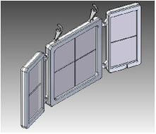
Next we needed a lid to prevent too much dirt or other harmful things from lowering the life expectancy of the station components. We had a piece of 24"x36" plexiglass and some aluminum brackets. We could not figure out an easy way of constructing a lid, so we decided to use a wood border and screw the plexiglass to the wood. This made it easy to screw hinges and handles on the lid for ease of access.(Fig 7) A final touch to station was to label the components, laminate numbers and velcro the numbers so they can be matched up to each component.(Fig 8) To make it interactive, those using the panel have to figure out or guess which numbers go to which components. We placed a laminated legend of all the components and what they do, along with the corresponding numbers, along with simple use and safety instructions.
-
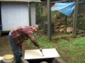
Fig 1: Bob getting his hands dirty painting the system!
-
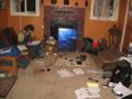
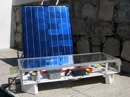
Fig 2:PV Learning Station Component Layout
-
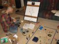
Fig 3: Bob wiring up AC disconnect
-
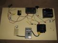
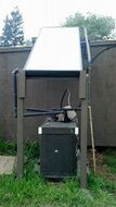
Fig 4: Solar Learning Station almost all wired up
-
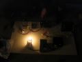
Fig 5: It's Alive! Testing AC part of system
-
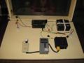
Fig 7: All done but needs labeling
-
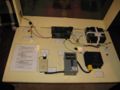
Fig 8: Laminated, Velcro labels
-
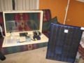
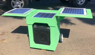
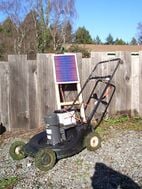
Fig 9: Ready for HSU!


Testing[edit | edit source]
The testing portion of our project was a difficult one that allowed us to apply what we learned to our next project. We had various testing scenarios, as we needed to meet the established criteria in addition to just having the darn thing work properly. We needed to test to make sure it worked, was portable, adaptable, and easy to comprehend as well as being safe and user-friendly. It obviously worked, but when testing it on our fellow students, a design flaw that occurred before popped up again. The female connector for the panel and the wires to the panel need to be of greater quality and durability. We fixed that. We proved that two people can move it around (in fact one can, as Bob continually put it in and out of his camper until Mother Nature finally complied with a beautiful day). We tested its adaptability by plugging in different AC(cell phone charger) and DC(a cigarette lighter cell phone charger) powered devices. The learning station is pretty easy to comprehend with clearly labeled components and simple descriptions. As far as safety, we have many disconnects and fuses. We also added instructions to turn the system on and off. Finally, students in ENGR 305-Appropriate Technology class stated that the hands-on aspect of seeing and following the components and electrical path was integral to their learning process. They even helped us identify the plug/connector problem and solve it!
Safety[edit | edit source]
For the best and safest use of this system, please take the following steps before starting use.
- Ensure that the two small silver switches and the larger black switch are off(down)
- No wires are connected to the battery.
- Ensure that the power Inverter is off.
- Ensure that the light switch is off.
Operating[edit | edit source]
When all these steps are taken, begin instruction. As always feel free to instruct the way you wish. As long as the safety instructions are followed, choose your own dialogue and order of steps.
- Ask the students to place the appropriate velcro number next to the corresponding component
- Once they are finished, you can plug in the panel to the female DC connector to the left of the station if facing it from the front
- At this point, you can decide which steps to take and in what order, but the following steps are some suggestions
- Plug a DC load device such as a cell phone car charger or other device into the female DC load plug between the battery and charge controller/monitor
- Flip the small silver switch near where the panel is plugged in to the ON position
- If there is sun, notice the DC device is charging or working. The monitor should show that the array current light is lit and the voltage coming in from the panel.
- Carefully connect the wire to the left of the battery with a piece of blue tape around it to the left (negative) point on the battery
- Carefully connect the wire to the right of the battery with a piece of red tape around it to the right (positive) point on the battery
- Notice the monitor showing the battery voltage light lit
- Flip the small silver switch below the battery to the on(up) position
- Turn on the inverter
- Flip the black switch to the on(up) position
- Flip the light switch to the on position and the light should light.
- Instruct as you wish
- Turning off
- Repeat all the steps but in reverse
- Troubleshooting-if components are not operating
- Using a voltmeter, during full sun, carefully check the voltage and current at every point possible on the station using the appropriate AC or DC selector on the voltmeter
- If the DC and/or AC voltage or current is not consistent throughout the system, note where the system is failing
- Choose to either replace/repair the parts and re-test or contact a CCAT associate
Budget[edit | edit source]
| System Cost Table | ||
|---|---|---|
| Component | Quantity | Cost |
| Voltage Regulator/Charge Controller | 1 | Donated |
| Voltage Meter | 1 | Donated |
| Solar Panel | 1 | Donated |
| Voltage Regulator/Charge Controller | 1 | Donated |
| Inverter 400w | 1 | Donated |
| Silicon/Latex Caulk | 1 | Donated |
| Plywood 24x36 | 1 | Donated |
| Nuts, Bolts and Screws | 3 | Donated |
| Handle | 1 | Donated |
| Wire Tubing | 1 | Donated |
| Zero VOC Paint | 1 | Donated |
| Copper Wire (12 Gauge) | 9 ft | Donated |
| Romex Wire | 3 ft | Donated |
| 10-15 Amp Fuses | 3 | Donated |
| Female and Male DC Plugs | 3 | $1.00 |
| Power Patrol AGM 18 Amp Hour Battery | 1 | $70.73 |
| DC Disconnect | 2 | $8.20 |
| Circuit Breaker/AC Disconnect 30 Amp | 1 | $16.08 |
| 30 Amp Circuit Breaker Fuse | 1 | $8.57 |
| Light Switch/Outlet | 1 | $8.57 |
| Outlet Box | 2 | $2.98 |
| Plexiglass 24x36 | 1 | $20.00 |
| Wire Connectors | 3 | $19.06 |
| Aluminum Brackets | 6 | $6.00 |
| Light Bulb | 1 | $2.89 |
| Total | $166.08 | |