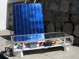
This photovoltaic system was designed to power a DC Vaccine Refrigerator at the hospital Centro De Salud in Parras, Mexico. Centro De Salud had a list of items that needed to be purchased at their hospital. Among these was a new vaccine refrigerator. After learning of this, the project group members set out to design a PV system for the hospital that could fulfill this need.
PV systems are well suited for vaccine refrigeration for a few reasons. PV arrays are becoming an increasingly popular alternative to gas generators for supplying energy to off-grid vaccine refrigeration because of their ability to create reliable energy that requires little system maintenance. According to the World Health Organization, PV refrigeration systems are much more efficient at maintaining internal temperatures in refrigerators than gas generators. This creates for an overall greater reliability of the refrigerator system. In the case of Centro De Salud, having a PV powered vaccine refrigerator could prevent vaccine spoilage due to grid power outages, which can be very costly.
System Specifications[edit | edit source]

These are the primary supplies used in the system:
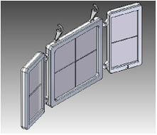
- 2 12V 40 watt Uni-Solar PV laminate panels
- Charge Controller 4.5 Amp
- Trojan Deep Cycle Battery 215 AH
- 6 gauge wires, 10 gauge wires
- Fuses
- Sun Frost RFVB-134a Solar Powered Vaccine Storage DC Refrigerator
For in depth explanation of these supplies refer to the Photovoltaics page on Appropedia.
System Calculations[edit | edit source]
Usually when designing a system, it is ideal to use calculations to figure out the appropriate sizes for the PV array, the charge controller, and the battery, and then purchase the supplies. In this case, the panels and charge controller had already been donated, and sizing the system was simply a matter of plugging in the numbers and seeing if the system was sufficiently sized for our load.
Where to get the values?
In order to obtain values for use in the system sizing calculations, research and testing is necessary. Often times, values for what your looking for can be found on a device that you are using. Other times, researching online may be necessary. If the values in your system calculations are inaccurate, they could throw off your entire system.
Load[edit | edit source]
The first thing to figure out when designing your system is how much does your load need? This system is for a DC refrigerator, and therefore an inverter is not needed to convert to AC. Designing a PV system for a refrigerator is a bit harder to plan for because of the fact that the refrigerators draw requirements are dynamic based upon the weather. In 70° F weather, this refrigerator pulls only 14 Amp Hours a day. In 90° F weather the refrigerator uses 23 AH/ day. According to the official Municipal Profile of Parras, the average annual temperature is 68° F with a maximum average temperature of 77.36 ° F in the months of June and July. However, some days the temperatures can spike. For this reason, calculations were done for both values, to be safe.
Array Sizing[edit | edit source]
For 90°F Weather[edit | edit source]
| 23 AH/Day | / | .85 Battery Efficiency | / | 4.5 Peak Sun Hours/Day | = | 6.01 Array Peak Amps |
| 6.01 Array Peak Amps | / | 2.1 Peak amps/module | = | 2.86 Modules in Parallel | ~ | 3 Modules in Parallel |
| 12V DC system voltage | / | 12V Nominal Panel Voltage | = | 1 Module in Series | x | 2.86 Modules in Parallel |
| = | 2.86 | Modules in Parallel | or | 3 Modules in Parallel | ||
For 70°F Weather[edit | edit source]
| 14 AH/Day | / | .85 Battery Efficiency | / | 4.5 Peak Sun Hours/Day | = | 3.66 Array Peak Amps |
| 3.66 Array Peak Amps | / | 2.1 | = | 1.74 Modules In Parallel | or | 2 Modules in Parallel |
Panels[edit | edit source]
First the two panels were tested with a multimeter for voltage and amperage. Each panel put out a maximum 2.1A and 20 Volts. Using P=IV we calculated that P=2.1A x 20V. Therefore P= 42 W. However, this value is not the real value for how much wattage each panel can put out. The reason is that all panels have a specific IV curve which gives the real possible output values of the panels. According to The Encyclopedia of Alternative Energy and Sustainable living, an IV curve is a current/voltage curve which expresses the possible combinations of current and voltage output of a photovoltaic device. Most PV manufacturers list the IV curve either on the panels themselves or online. However, because the panels used in this system are no longer in make, it was impossible to find the real IV curve of the panels. Fortunately, for calculating array size, the only information needed from the panels is the module peak amps, and the nominal module voltage. Therefore our module peak amps are 2.1A, and our nominal voltage for the panels is 12V based upon our measurements with the multimeter. Because this project already had the panels, array sizing calculations were done only to measure if our system could handle the loads required.
Battery Efficiency[edit | edit source]
Deep Cycle Lead Acid batteries have an average efficiency of 85%
Peak Sun Hours[edit | edit source]
Peak Sun Hrs/Day According to the Advanced Energy Group website, the average low peak sun hours in this part of Mexico are between 4 and 5 hours. Therefore 4.5 peak sun hours was the value used to calculate our array size.
Controller Sizing[edit | edit source]
Sizing the control for this system was done to check to see if the controller donated to this project would be enough to handle the amperage produced by the panels.
What is the Module Short Circuit Current?
The Module Short circuit current is the absolute maximum current that each panel can produce. Some panel manufactures may list this on their panels. For the Uni-Solar laminate panels used at Centro De Salud, a multimeter was used on a clear sunny day to determine the peak amps of the module. The peak amps measured were 2.1amps per module. The short circuit current should be slightly greater than the peak amps module, and therefore a value of 2.5Amps was used to calculate the system's needs.
| 2.5 module short circuit current | x | 2 panels in parallel | x | 1.25 | = | 6.25 Array Short Circuit Amps |
| 280 Total DC Watts | / | 12 DC System Voltage | = | 23.3 Maximum DC load amps | ||
Interpretation
The charge controller should be able to handle a larger amperage than the array short circuit amps, which in this case was 6.25 Amps. How then can a 4.5 Amp charge controller be used in this system when the array short circuit amps is 6.25? The answer is that this equation over compensates for the size of the charge controller to be safe. In reality, the panels are not expected to exceed 2.2A each at the most, even though 2.5A was used for the module short circuit current. Also, the 1.25 in the equation above is used as a saftey percaution so that the controller is sufficiently sized. So, without that saftey percaution, this system actually has an array short circuit current amp value of 4.4A, which means that the charge controller is just barely large enough for this system. However, when designing your system, it is definetely a better idea to oversize your charge controller, than undersize it.
Battery Sizing[edit | edit source]
A battery must be appropriately sized for the system. Days of autonomy, or the amount of days that your battery can power your system without help from the panels, must be factored into the battery sizing equation. If the system has too small of a battery, then during times when the panels are not creating your energy reserve will be small. For lighting systems, where it is not essential to have lights on, it is acceptable to have a small reserve. However, for systems like the vaccine refrigerator that power essential loads, it is important to plan for as many as 5-7 days of autonomy. It is possible to oversize the battery as well. Deep discharge batteries are designed to discharge, and then to be fully recharged. When a battery gets discharged too deep, for too long, it drastically effects the batteries efficiency and total life cycles. Therefore battery sizing is an essential part of designing a system. By properly sizing the battery to your systems needs, the life of your battery, and reliability of your whole system are greatly improved.
Trojan Deep Cycle Battery
The 215 AH trojan deep cycle battery is designed to be safely discharged up to 80%. Battery maintenance is necessary to maintain your batteries life and performance. In order to check how far the battery is discharged,voltage ranges and corresponding percentage discharge rates are posted on a PDF available from the Trojan company. The minimum safe voltage for this battery is 11.66V. For more info on battery maintenance follow this link: [1].
Battery Sizing Calculations
| 23AH/day | x | 7 Days of Autonomy | / | .80 Discharge limit | / | 215 Battery AH Capacity | = | .936 Batteries in Parallel |
| 12V DC system Voltage | / | 12V Battery Voltage | = | 1 Battery in Series | x | 1 Battery in Parallel | = | 1 215 AH Battery |
Interpretation:
The vaccine refrigerator at Centro de Salud qualifies as a critical load, and therefore, 7 days of autonomy have been allotted for by using this size battery. The only problem is that it may be difficult, once deeply discharged, for the PV array alone to recharge the battery. In Parras, Mexico it is often cloudy and rainy for days at a time, which means that if there are many consecutive days without sun the panels alone may be insufficient to recharge the battery.
Back-up Plan
It is generally a good idea, in stand alone PV systems, to have an alternate method of electrical generation for critical loads. Often times, gas generators are used as a back up, in times of emergency. However, because Centro de Salud has access to the grid, a battery charger has been purchased for situations when the battery discharges to dangerously low levels. The battery charger is a rectifier that converts AC into DC allowing one to plug the battery into an AC socket in the wall for charging.

Wire Sizing[edit | edit source]
The two 12V Panels are wired in parallel, to keep the panel´s voltage about the same as the battery´s. On the negative side, a 5A fuse is conncected for saftey purposes. Should anyone accidently cut the wires so that it creates a circuit, the fuse will break as the current surpasses 5A. From there the wires connect to the charge controller. Then two wires leave from the charge controller to connect to the battery. Once again, a fuse is fastened to the end of the negative terminal of the battery. This is to ensure that anything that passes to or from the battery must first pass through a 20A fuse. It is important to size your fuses appropriately. If the fuse is undersized, it will blow to frequently, creating a hassle to maintain, and in the case of the refrigerator, could be dangerous to the internal temperature. Therefore, its ideal to size your fuse, just over your surge current, which for the fridge is 15 amps. That way, the fuse wont blow everytime the compressor kicks in, but it could still save someone's life in the case of an accident. From the battery, the wires flow to a switch, allowing for one to shut off flow from the battery to the fridge for maintanence or in an emergency. This is a simple, yet essential part of a system. Finally, the cables run from the switch to the back of the fridge.
System Design[edit | edit source]

Ampacity vs Voltage Drop[edit | edit source]
Ampacity and voltage drop are two important factors when sizing the wiring for a system.
Ampacity[edit | edit source]
Calculating ampacity determines the minimum overcurrent protection needed in the wires. The reason why the equation multiplies the total load amps by 1.25 is so that the conductor never carries more than 80% of its rated capacity. This is also done to handle any extra current produced by the panels caused by reflection or exceptionally sunny days. The short circuit current must be multiplied by a second 1.25 to ensure the proper size conductor and to meet code[verification needed]. It is essential to ensure at the very least, ampacity is measured for your system's wiring.
Determining Ampacity
Wire Run from Array To Battery
| 2.1A Module Short Circuit Current | x | 2 Modules | 4.2 Total load amps | |||
| 4 Total Load Amps | x | 1.25 | x | 1.25 | = | 6.25A |
Based on tableswhat tables?, 14 AWG wire is needed at minimum to handle an ampacity of 6.25A
Introduce and describe how these tables work, and work on the table formatting.
| 23A | x | 1.25 | = | 28.75A |
Based on tables, 10 AWG wire is needed at minimum to handle an ampacity of 28.75A.
Voltage Drop[edit | edit source]
Voltage drop is a loss voltage due to a wires resistance and length. When planning a system it is always safer to use the voltage drop values instead of the ampacity values because voltage drop gives the maximum amp capacity. Voltage can drop over a matter of feet, so its ideal to have your panels close to whatever you are powering, to ensure minimal voltage drop as well as minimal cost. The lower the wire's gauge, i.e. the larger the wire, the longer the wire can be before significant voltage drop occurs.
Determining Voltage Drop
Based upon voltage drop values obtained from tables what tables and how do you use them, for 2% Voltage drop over 60 feet of length for 5 amps, 6 gauge wire is needed.
Constructing the system[edit | edit source]
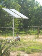
Orientation of the Panels[edit | edit source]
It is important to orient your panels properly so that they receive the maximum amount of solar radiation throughout the year. Direction and angle towards the sun are two important factors when determining where to face your panels.
Direction[edit | edit source]
In the northern hemisphere, panels should be faced southward and the opposite for the southern hemisphere. However, for maximum efficiency, the panels should be faced towards true direction, not magnetic direction. True south, or true north, can be found simply by using a compass and a declination map reading based on your location, which tells you how much to adjust your reading for magnetic direction. The National Geophysical Data Center has a great online declination calculator that allows one to calculate declination based upon time and location. This can be found at this link: http://web.archive.org/web/20080516100942/http://ngdc.noaa.gov/seg/geomag/jsp/Declination.jsp
Angle towards the Sun[edit | edit source]
Photovoltaic panels produce the most power when perpendicularly facing the sun. For this reason it is important to mount your panels so that receive that greatest perpendicular exposure to the sun. When deciding what angle to mount your PV array, it is generally a good idea to use the corresponding latitude of your location. Because Parras, Mexico resides at 25°N 102°W, this system's panels were mounted at a 25°. However, depending on your systems needs, it may be beneficial to adjust your panel's angles as much as 4 times a year to boost your system output. Whole Sale Solar (http://www.wholesalesolar.com/products.folder/mount-folder/mount-info.html) recommends adjusting your panels as follows:
- February 5th - Set to same angle as your latitude.
- May 5th - Set at the same angle as your latitude minus 15°. At noon the panel will be almost horizontal to the ground.
- August 5th - Set at the same angle as your latitude.
- November 5th - Set at the angle of latitude plus 15°. This tilts your panels towards the sun as it travels low in the southern sky during the winter.
Connecting the Wiring[edit | edit source]

Connecting the wiring proved to be one the more challenging tasks in this project. Most wire to wire connections use wire nuts to safely connect the two cables. However, 6 gauge wires are extremely thick, and no hardware stores in town carried the wire nuts at the size we needed. A secure waterproof connection was required especially for the wires on the roof that connect to the panels, which will receive large amounts of rain. Instead of using wire nuts, the wires were simply connected with electrical tape. Then PVC piping was used to cover the connections, making it both water and sun resistant. Then with zip ties, the pipes were held together and to the panel mount to keep them from blowing in the wind. While not a perfect solution, the PVC pipe should prolong the life of the system's wiring connections greatly, as well as reduce the wear on the wires.
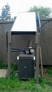
The Mount[edit | edit source]

The mount is crafted out of wood. It was built by a local carpenter in Parras. It has hinges fastened to the bottom so that the panel's angles can be adjusted. However, as of now this systems mount is fixed at 25°. Future groups maintaining this system, may choose to create notches in the back supports of the mount so that the panels would be able to be adjusted seasonally. The mount is put on the highest roof at the hospital, and there are no obstructions such as trees or buildings that can interfere with the panels. However, because of high winds, it was essential that this mount was fastened to the roof. One way to this is to use tar to fasten the mount down tight. However, this mount was fastened down with 2 cables running from both the front and back of the mount that fasten to the edge of the roof. Additionally, 3 concrete blocks are laid across the bottom of the mount to help weigh it down.
The Refrigerator[edit | edit source]
The refrigerator arrived after all the project participants had left Parras. The only remaining HSU student, Jeff Kinzer, agreed to do the installation.
The SunFrost refrigerator arrived at the Muñíz residence on Monday, August 1. The refrigerator remained there while we searched for a truck to carry the package to the hospital. By the time I was able to get access to a truck, the refrigerator had already been moved. Upon going to Centro de Salud Fridady August 5, I was informed that no one would be in the laboratory until Monday. I returned Monday to discover the refrigerator had been installed by Antonio, the hospital technician.
The refrigerator is fully installed and working. Currently (18:09, 7 August 2006 (PDT)), the unit is set at 40° F. There is no method for monitoring the internal temperature. Tomorrow, August 8th, Antonio will be installing a thermometer in order to measure the refrigerator for a week before using the system for vaccines. Antonio reports that the solar panels are maintaining 13.16V.
Photographs of Completed System[edit | edit source]
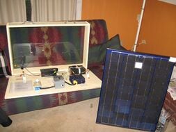
-
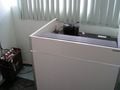
Refrigerator with battery
-
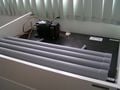
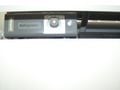
The top of the unit, with compressor and condenser.
-

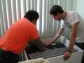
Antonio, Centro de Salud technician, and the Sunfrost refrigerator.
-
Final inspection of the connection
-
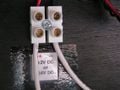
DC connection to PV system on the top of the unit
-

Refrigerator compressor
-
Temperature adjustment dial set to 40 degrees F
-
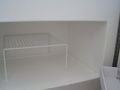
No vaccines yet
-
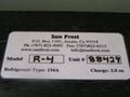
SunFrost unit placard


Philanthropic Aid (updated 2007)[edit | edit source]
Fed Ex reimbursed us for the shipping of the refrigerator on the basis of this project being a philanthropic aid project. When doing a project that qualifies under this category, be sure to request any major buisnesses like Fed Ex about the possibility of getting free or at least discounted shipping. Often times these companies are looking for projects to boost their PR, and would be willing to contribute.
Costs[edit | edit source]
| Quantity | Materials | Cost $ | Total |
|---|---|---|---|
| 2 | 12v 40 watt Uni-Solar PV laminate panels | 150.00 | Donation |
| 1 | RFVB-134a Solar Powered Vaccine Storage DC Refrigerator | 1200.00 | Donation |
| 1 | Charge Controller 4.5 Amp | 45.00 | Donation |
| 1 | Trojan Deep Cycle Battery 215 AH | 240.00 | 240.00 |
| 1 | Battery Charger | 51.00 | 51.00 |
| 1 | Mounting Frame for Panels | 50.00 | Recycled |
| 60 Feet | #6 gauge wire | 1.33 | 80.00 |
| 7 Feet | #10 gauge wire | 2.14 | 15.00 |
| 1 | 5 Amp Fuse | 3.00 | 3.00 |
| 1 | 20 Amp Fuse | 3.00 | 3.00 |
| 1 | On/Off Switch | 10.00 | 10.00 |
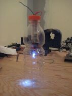
| 1 | 60watt DC light bulb to test system | 2.00 | 2.00 |
| Misc. | Zip ties, duct tape, electrical tape, tubing to cover wire connections | 25.00 | 25.00 |
| Total Cost | 429.00 | ||