Executive Summary of Project: One Laptop Per Child (OLPC), a non-profit organization, has been distributing XO-laptops to children in third world countries. Whenever consumers purchase an XO-laptop for themselves, OLPC also provides one to a child somewhere in the world.
The problem was the need to power these XO laptops in communities where access to electricity is limited to only schools, or non-existent altogether. The proposed solution was the use of solar panels to harness the sun's energy to charge the computers. This project involves the production of a robust, waterproof solar panel casing that produced sufficient power to energize the laptop, while remaining relatively easy to build and inexpensive.
Four initial prototype designs were drafted on the Solid Edge software and ultimately, the fourth design, the Hook model, was chosen because it addressed almost all of the criteria initially set. The cost of the final prototype resulted to approximately $89.94, which was slightly higher than the $80 budget constraint for the project. The cost was minimized as much as possible through the use of regular everyday items, such as hot glue, piano hinges and Styrofoam and most of the price was associated with the prototyping plastic.
The ultimate economic goal of the project was to create solar panels that could be built for under $50, and this goal could be achieved through mass production and the use of a cheaper prototyping machine. The estimated cost for making each unit under mass production circumstances was estimated to be $32.64.
The project met most of the goals that were established at the beginning of the assignment in terms of creating a rugged design; however, testing of the final product proved inconclusive due to extenuating circumstances regarding recent weather.
Team[edit | edit source]
XO-Laptop Solar Panel Design
APSC 100 Module 1 Project Report
Written by: Group 213:F
- Donald Kester
- Philippa Krahn
- Nathan Neeteson
- Daniel Skiland
- Xin Zhang
Report prepared for:
- Dr Joshua Pearce
- Nabeil Alazzam
Honesty Statement[edit | edit source]
"We do hereby verify that this written report is our own individual work and contains our own original ideas, concepts, and designs. No portion of this report has been copied in whole or in part from another source, with the possible exception of properly referenced material."
Introduction[edit | edit source]
The first task required for the project was determining the basic power needs, dimensions, and overall aesthetic of the laptop, as well as meet any other needs of the laptop users. The XO laptop is a durable, low-powered laptop with a very advanced network structure. It is designed and manufactured by a non-profit organization called One Laptop per Child (OLPC). OLPC designed this laptop with the specific purpose of being delivered to underprivileged and under-educated children in third world countries, to help with their education and general social development.
The problem with this system is that the areas for which these laptops are designed to be delivered generally do not offer access to reliable electricity for all the residents. As a result, children cannot use their laptops unless they are able to charge the laptop at school. This undermines the entire of the XO laptop. One proposed solution to this problem was a hand crank that would be affixed to a table or edge via a vice and a crank could be turned to generate electricity for the laptop. This idea was highly unfeasible and production stopped soon after it began.
A more viable solution to the problem is an attachment that uses solar panels to convert energy from the sun into power for the laptop. This project is not the first attempt to make such a module. Most of the other designs that involve solar power for the XO laptop are built by hobbyists from parts bought individually from either retail stores or from online auction sites, and are not nearly durable or environmentally-protected enough to be viable prototypes for use in a third world country. There are also companies that produce solar power attachments, but they are profit-seeking entities that would not share their design specifications with the public, as that would undermine their sales and possibly drive them out of business. Therefore, a new design must be created by the project team using a variety of research on how solar panels work to design an efficient, cheap, durable, and replication-friendly prototype.
The prototype will be built using solar panels purchased in bulk by the Project Manager, an acrylic covering purchased from a local hardware store to protect the panels but also let light through, a frame constructed by the rapid prototyper, and various hinges, screws, washers, and bolts purchased from a local hardware store.
Problem Formulation[edit | edit source]
ince there is a long list of criteria that were to be fulfilled for this project, it is important to address all of the concerns when designing the prototype. It is essential to remember the needs of the users of the final product, in this project specifically referring to children living in third world countries with limited access to electricity.
One of the more important points is that the attachment must be well-matched to the laptop. To accomplish this, the proper circuit must be purchased and the properly configured to convert the power generated by the panels into something usable and compatible with the XO laptop. It must also produce the correct amount of power so that the laptop is not over-charged, which would mean the prototype is more expensive than it needs to be, but that the laptop can run while attached and charges at an acceptable rate.
One of the biggest concerns with the laptop is the environmental conditions into which the laptop and attachment will be thrust. The circuitry within the laptop is extremely sensitive to moisture and the slightest amount of water leaking inside could render the entire apparatus ineffective. The materials the attachment is built from will be totally waterproof and separate pieces joined together will be sealed using special caulking purchased for all groups from a local hardware store. It is absolutely essential that the attachment be completely waterproof. Another concern is high temperature. Most areas that the laptops are sent to are somewhat close to the equator, meaning they experience extremely high temperatures almost year-round. Studies have shown that the efficiency of solar panels decreases if they are heated to extreme temperatures and especially if they lack sufficient cooling/air flow systems. While it would be completely unacceptable to allow air to travel in and out of the system, bringing in moisture, some room underneath between the panels and the casing will be left or insulated to allow heat to transfer from the solar panels.
A concern that other groups had in the formulation of a prototype was the issue of inclining the panels directly toward the sun, and changing the angle of inclination depending on the latitudinal location of the laptop. While it is true that optimizing the angle of inclination of a solar panel does increase the power output, it was found that within a 30⁰ band around the equator, it was nearly as effective to just leave the solar panels lying flat on the ground, with minimal loss of power. Inclining the panels would require additional material and more potential for failure in the event of an accident, therefore it was decided that the optimal solution in terms of cost-benefit would be to simply not implement a system for inclining the panels.
A major constraint of this project is that the cost of the prototype must be kept incredibly low, such that any other features other than the principle requirements, durability and adequate power generation, are not feasible. The XO laptop itself is an incredibly inexpensive piece of equipment and it would make absolutely no sense if the module intended only to power it cost more than the laptop itself. A related requirement is that the product must be easy to reproduce using RepRap prototypers. This would allow a village to purchase their own prototyper and then construct solar power modules (among other things) at a far lower cost than constructing them elsewhere and shipping them in. Ease of manufacture will also contribute to lowering the final cost of the prototype.
The XO laptop is expected to last a number of years, at least for the majority of a child's schooling. Therefore, it is reasonable for users to expect the solar power module to last as long, if not longer, than the XO laptop itself. Solar panels have an extremely long life if not damaged, and so should the casing designed to protect them. The laptop and attachment should be seen by the residents of third world countries as long term investment.
In addition, it was agreed upon that the aesthetics of the attachment are an integral part of the design process. An attachment that is pleasing to look at and looks as though it matches the laptop would be preferable over an attachment that was designed without aesthetics in mind. Children are the primary users of the product, so it should appeal to them visually.
Design Considerations[edit | edit source]

Taking into account all of the various criteria of functionality, durability and aesthetics for the solar panel, another major consideration is the existence of an optimum angle at which the panel should be placed. This angle, which exists because the panel caters to children in different parts of the world, was determined to have a less profound effect on the power output than initially expected. Although ideal panels exist, which can track the movement of the sun throughout the day and produce 40% more power during the summertime and 10% more in the winter4, such panels induce unnecessary cost to the project.
Optimum angle = Latitude - 2.5° (summer)(1)
Optimum angle = Latitude *0.9 +29° (winter)(2)
Equations 1 and 2 summarize the optimal angle to position a solar panel during summer and winter. However, further research showed that the application of the two equations would increase the efficiency and power output of the solar panels by a mere 4%2. Laying the panels flat on the ground would increase the longevity of the device, as well as decreasing the complexity of production.
Additional notice should be taken into the fact that the distribution of XO laptops throughout the world is also not even. Figure 1, which was tabulated from data taken directly from the One Laptop Per Child website, shows that over 60% of the laptops are allocated in two countries in South America. The uneven distribution further emphasizes the impracticality of having angled panels that can be adjusted for any part of the world.
Design Prototype 1 – Hemisphere Panel[edit | edit source]


Barring all of the design criteria for the panels in mind, the first Hemisphere design model encompasses a very rigid structure and support for the solar panels. It was also very durable because it was made of few parts and only one moving part, which is very simple. This design allowed for easy positioning of the solar panels to allow for maximum power output; it was also meant for a client for whom transportation is not required due to its quite large and bulky nature. The major disadvantage of this model was its impracticality due to the solid hemisphere in the prototype. The sphere itself would take an incredible amount of plastic to construct; therefore, making it long lasting, but expensive to produce. Thus, this design was not an ideal solution for the problem.

Design Prototype 2 – Flap Panel[edit | edit source]
The sleek design of the flap model could have been very easy to construct and looks relatively stylish to accompany the XO laptop. It would have also used far less plastic than the previous design. The flap connects to the holder of the solar panels by a hinge, which, when propped up, can support the panel at an angle, or just remain flat for convenience during the day. This design had several disadvantages, however. Since the flap itself was very long, it had a large moment of inertia and consequently would not be a very strong support. Additionally, neither the 3-D printer nor rep-rap machines likely be able to produce the panel casing and the flap in one piece because it spanned too long of an area. Hence, the flap model was not chosen.

Design Prototype 3 – Clamshell Panel[edit | edit source]
The third design met the criterion of being rugged and durable. It could have also been easily transported from place to place because it could be folded up into an easy to carry shape and provided protection to the panels during transportation. The design's pieces would not be too long to be produced by the rep-rap, like the second design. The folding parts could also be set to catch a variety of different angles from the sun. However, it was still very bulky and wasn't small enough for a child to carry around. It also required a lot of material. Ultimately, the Clamshell model would prove useful if its intended use was to stay at home and not to be carried around with the XO laptop, so it was not chosen.
Design Prototype 4 (Chosen Design) – Hook Panel[edit | edit source]
In the fourth design, the side panels fold into the centre, protecting the solar panels within the casing. The hooks on this design also contribute to ease of transport because the attachment itself can be hooked onto the handle of the laptop.
This design has a number of other features designed for ruggedness. Within the case, there is empty space between the plastic and the solar panels; this is because the solar panels are quite thin. The space within the case will be filled with foam used as padding so that in the event of the attachment getting dropped or knocked around, the shock will be absorbed so that there is some protection provided to the solar panels. As mentioned above, edges where the pieces join will be sealed using a transparent silicon caulking.
The above design is further an improvement on the others because its parts are all small enough to be constructed by the rapid prototyping machine. Another advantage of this design is that its construction should be relatively inexpensive.
Lastly, aesthetic appeal was taken into consideration when coming up with this design. With rounded edges and the opaque plastic casing, it looks as though it belongs with the XO laptop, making it more attractive especially for children.
While researching what previous groups have constructed as their final project, we found there were several aspects of their designs that we could improve upon. They all seemed to focus very much on propping the solar panels up to an optimal angle to absorb as much of the sun's energy as possible. However, we discovered that the angle would end up being approximately 0⁰ (horizontal) for the majority of the users of the attachment. For this reason we have not put nearly as much consideration into this area of the product's design.
While the above design has merits, it also left significant room for improvement. Before we begin construction, there are a number of materials and possible design changes that we are going to look into. The first of these is the use of sheets of acrylic on the flat bottom of the casing. This would reduce costs considerably, with little loss of aesthetic appeal and strength. With this change, the rapid prototyping machine would only be used to make a frame that would go around the sides of the casing, while its top and bottom would be made of different materials. This would require considerable changes to the current Solid Edge design pictured above.
Also in the above image, the hinges are simply plastic pieces protruding from the edges of the casing. This is not ideal because there needs to be some way for the wiring within the case to make its way between the three panels. The solid hinges have no space for this, and making them hollow would not be possible with the rapid prototyping machine. If it is at all possible we will be looking into some method of threading the wiring through the hinges so as to protect them from wear and tear that could occur outside the case. Additionally, we will be looking for one long hinge to be used on each side of the case as opposed to the two smaller hinges currently in the design. This would make construction simpler, with fewer parts, and increase strength.
Since the proposal presentation, we have realized that our design is good conceptually but still needs a considerable amount of work before it can be constructed. The window-pane style of casing was abandoned for a more streamlined and plastic-efficient frame. One change that we will need to consider carefully is the possibility of actually using fewer solar panels. This would certainly cut down costs where unneeded solar panels are being used, however it would also require drastic design changes if it were decided that fewer solar panels would optimize performance and minimize cost.
Materials[edit | edit source]
There were a wide variety of materials used in the construction of the prototype, including movable parts, plastic for the case and acrylic covering. Originally, the proposed hook panel design required a solid casing material to be provided by the 3-D printer and consequent rep-rap machines. The prototype had to be altered to use the plastic only for the frame due to cost constraints. Additionally, many extraneous materials, such as hinges and wiring, were originally to be purchased from the McMaster-Carr website, but simpler, everyday items were used to minimize the complexity and economic weighting of those items.

Frame[edit | edit source]
White PVC was used to make the edges and backing of the solar panel, with a thickness of 3mm, with the exception of the groove at the top that is 3.175mm deep and 1.5mm thick, this sizing created the perfect balance between strength, flexibility and cost. This thickness was ridged enough to support the solar panel and protect it during drops and so that it would not readily deform. The reason PVC was chosen was because it was a better choice than ABS due to it being half the cost even though it was moderately more fragile.
Covering and Backing[edit | edit source]
The covering was made out of 1/8 inch thick cast clear acrylic. It was chosen because of its resistance to UV weathering, inexpensive nature, abundance and ease of manufacture. Scratch-resistant acrylic, which was originally chosen to prevent slight scratches on the face of the panel to affect power output, was been scrapped in favour of regular cast clear acrylic since it was significantly cheaper. Acrylic was also a better choice than glass due to its lower cost and weight and greater resistance from scratches and shattering.


Solar Panels[edit | edit source]
The solar panels were chosen by the project coordinator, for all groups currently participating in this project were standard Schott solar 4x4in panels. These panels were extremely fragile and therefore had to be mounted to Styrofoam for protection. Their peak power output in the sun is 2 watts.


Hinges[edit | edit source]
The hinges used were four 4cm piano hinges, with two being attached on each side through the use of glue. The hinges were chosen for their durability, cost and low profile that conformed to our original streamlined design. The recommended hinge for a production model would be one made from PVC in the RepRap with a possibility for the wire to snake through the hinge in order to preserve a watertight seal and increased lifetime.
Wire[edit | edit source]
The wire used in the panel was a clear plastic sheathed copper of approximately 16 AWG. The wire was chosen to go through the hinge in the production model so that it would last through a reasonable amount of wear and tear.
Sealant[edit | edit source]
The sealant chosen for our project was clear silicon caulking; the silicon caulking was also used to secure the solar panels and as a cushion between the Styrofoam backed 4x4in panel assemblies. It allowed for an appropriate synergy between shock absorption due to movement and rigidity. This sealant would be used in the production model.
Glue[edit | edit source]
The glue used to initially secure the front and back plates before sealing was hot glue from a glue gun. This glue provided adequate strength for the prototype; however, for a production model, super glue or epoxy, which last longer, should be considered.
Solder[edit | edit source]
The wires joining the solar panels were connected in series using standard tin-lead solder.
Styrofoam[edit | edit source]
Regular packaging Styrofoam was acquired and used to help cushion the solar panels against impact within its case. It was chosen based on the ease of access to Styrofoam and because it would be relatively cheap to acquire almost anywhere.


Construction Procedure[edit | edit source]
The first step in the construction procedure was the creation and editing of the final Solid Edge design. The original concept design underwent a significant change because of the volume of plastic it would have used. In addition, acrylic was used for the panels on the front and back of each segment of the attachment. This meant that much less of the rapid prototyping plastic had to be used, so that only a thin frame was needed for each segment.
Once the frames had been constructed by the rapid prototyping machine, the assembly of the solar power attachment began. The first step was to glue the solar panels themselves onto squares of Styrofoam, in order to give them some protection during the construction process, as they are very brittle. The acrylic sheets were then cut into the correct sizes to fit onto the plastic frame at the front and back.[1] A jigsaw and a band saw were used to cut the acrylic pieces, which were then shaped more precisely with a belt sander. The acrylic back was then attached to the plastic outer frame using hot glue.
The next step in the construction process involved placing the solar panels into place. Since caulking was used as the sealing for the panel, the styrofoam and solar panels were also held in place using caulking. Another change that was made to the design during construction was the addition of small "fences" of acrylic that ran upright between the solar panels within the casing. The acrylic front panel would ideally rest on the fence of acrylic, not the solar panel, and any downward force applied to the casing would then be absorbed by the fence. This system was put into place so that the panel would never have any force applied directly to it so that there would be less chance of it breaking.
After this step, hinges were placed on the casing. It would have been preferable to attach the hinges very securely with screws; however, this would have required holes to be put in the casing, compromising its waterproof seal. Because of this, and the fact that the casing was very thin and could potentially break with screws in it, the hinges were attached using hot glue.
Once most of the casing was in place, the solar panel leads were soldered together to complete the circuit. They were soldered in series so that the greatest voltage would be produced by the attachment, allowing the laptop to charge even in sub-optimal conditions. The leads ran through grooves in the fences between the panels, and going from one segment of the attachment to the other, a wire ran through small holes in the casing itself. With the circuit completed, we then were able to attach the power cord that would plug into the laptop.
The final step in the construction process was placing the acrylic front on the attachment with hot glue. This seal was less than perfect, however due to time and material restrictions, we were not able to use a method that would result in a more waterproof seal.
Problems in Construction[edit | edit source]

While the final product turned out well, a number of problems were encountered during construction. The biggest problem was that the solar panels did not come encased, and were extremely brittle and easy to break. This would not be a problem that could be solved in the future; the only real solution is to handle them as little as possible and put them into place as the very last step in construction. This realization occurred after the attachment had already been built, since many of the solar panels were damaged even during shipping, and some were broken during construction.
Other problems that occurred during construction were due to the tools that were available. One of the major problems was that we needed to seal the casing with caulking, however, there was no caulking gun available. As a result, far too much caulking was used. This wasted one of our materials and made the final product proved much heavier than it needed to be.
Another problem that arose was the need to use hot glue to seal the different components of the casing together. A different type of glue would have created a much better seal, but hot glue fit into the budget while other types would not have. In addition, the small strings that came off of the hot glue made a mess within casing of our attachment. These strings even got on top of the solar panels, which was not ideal because it blocks the sun's rays slightly from them.
As mentioned above, the hinges used were not ideal hinges. It would have been a better choice to use one long hinge on either side of the central panel in the design, in order to simplify and strengthen the attachment. While this was the ideal solution, such hinges were not available and two hinges had to be placed on either side.
Lastly, the wiring between the three panels of the attachment was another weakness in its design. It could have been made much more secure by using thicker wires going between the panels. The best solution would have been to thread the wire through the hinges, so that there would be no potential for the wire getting ripped out or cut accidentally. Certain constrictions prevented an improved design included restrictions on materials, tools, and time.
Testing[edit | edit source]
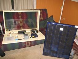
The planned tests for the Solar Power module required good weather (or a UV providing light), a voltmeter, an ammeter, and the XO laptop. The planned test procedure was to bring the solar module outside in the morning, midday, and afternoon of a sunny day, and at each time hook up the module to the voltmeter and ammeter and take readings of the current and voltage generated, as well as to hook it up to the XO laptop to gauge the degree to which the module could charge the laptop.
Unfortunately, due to extenuating circumstances caused by inclement weather between testing and presenting, effective power generating tests for the solar panel has been inconclusive. However, we it was verified that a current could run through the panel wiring; thus, in theory, the panels should be able to generate electricity. Additionally, impact testing was conducted from heights up to 3 feet, after which the module was not visibly damaged or marked and was still capable of carrying a current.
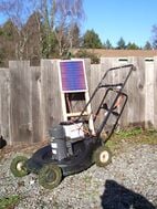
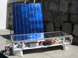
Final Product and Future Considerations[edit | edit source]
The final product fulfills most, if not all, of the original design specifications. It is rugged, able to withstand minor impacts that may occur during transportation, it is fairly lightweight so that a child would be able to carry it long distances with no difficulty, it is inexpensive, coming well within the desired budget if prices are altered for mass-production, and most importantly, the design and manufacturing instructions are simple enough that with a Rep Rap and some basic materials, anyone can produce our product.
However, there are certain changes that could be made to the prototype that would increase the durability and functionality of the design. A major problem during construction is the fragility of the solar panels themselves. Pre-coated solar panels are prohibitively expensive, so the most economical solution to this problem is to leave the solar panels untouched for most of construction, and then place and secure them at the last possible moment before sealing the module shut. This would minimize the chances for damage to inadvertently be done to the panels. Another problem is the high volume of caulking that was used as padding and sealant in our design. The prototype could probably be just waterproof and secure with less caulking, which would bring down both the price of the prototype and the weight, making it easier to carry. A further improvement that could be made is a greater consideration for aesthetic appeal. In the current design, aesthetic appeal was a last minute afterthought in the design, and while the product does look pleasing while shut, when open the acrylic fences, caulking, and wiring are all visible, which is not desirable. Finally, a feature that could be added in future products is one that we discarded in the planning phase: the ability to tilt towards the sun. While the current model is perfect for locations that are close to the equator, there is a market for models that can tilt, which would work more efficiently in areas farther away from the equator.
Economic Analysis[edit | edit source]
One of the main goals in this project was to minimize costs. This was accomplished by reducing material, using less expensive materials and assuming mass production of the final design. 42 solar panels between the three groups cost $150, making them approximately $3.50 each. We used eight solar panels in our design, which cost roughly $28 for the prototype.
Prototyping plastic cost $6 per cubic inch in the prototyping machine. Each of our walls for the design were 9.45 inches long, by 0.72 inches high by 1/8 inches thick. This was equal to 0.8505 inches3. The ten walls required for the frame accounts for 8.505 inches3. Subtracting the overlapping corners where the walls meet (1/8 by 1/8 by 0.72 inches) and the groves for the acrylic to sit in totals to 7.14 inches3. This total volume of prototyping plastic came out to approximately $42.84.
The protective cover and base was made a sturdy acrylic. The prototype required a 12x24 sheet. A 12x48 sheet cost approximately $12; therefore we used $6 worth of acrylic.
As for miscellaneous parts, hinges cost $1 each. Four hinges were used in the casing's design. Caulking cost $7 for a 10oz tube and we used around $6 worth. The output plug cost $2. For the other small parts including glue, wire and Styrofoam, another $1 is added to the total.
Please note that the costs for miscellaneous parts, acrylic and prototyping plastic costs are extreme over-estimates and are only accurate for the prototype model. Significant cost reductions can be made during mass production. However, the grand total for the prototype comes to $89.84, which is $35 more than where we should be. This goal of keeping the design under $50 should be able to be reached with mass production and reducing materials in the final designs.
Actual costs for prototyping[edit | edit source]
| Part | Base Price | Quantity/Amount | Cost |
|---|---|---|---|
| Solar Panels | $3.50 each | 8 | $28.00 |
| Prototyping Plastic | $6 / in3 | 7.14in3 | $42.84 |
| Acrylic Sheet | $12 per sheet | ½ sheet | $6.00 |
| Hinges | $1.00 each | 4 | $4.00 |
| Caulking | $7.00 per tube | Liberal use | $6.00 |
| Output Plug | $2.00 each | 1 | $2.00 |
| Wires, Styrofoam, glue and other miscellaneous parts | N/A | N/A | ~$1.00 |
| Total | $89.84 |
If this design was selected to be massed produced in third world countries, there would be a significant cut in the cost to build the design. When purchased in bulk for mass production, the solar panels will cost about $2.00 each, therefore $16.00 for all of them.
Using a Rep-Rap machine, prototyping plastic costs about $9/lb, which is equal to $0.34/cubic inch. Due to the extreme reduction of cost of the plastic, it is actually cheaper to use as a base instead of acrylic. So 19.73 in3 of plastic is added which ends up costing $6.71. This brings the total volume of plastic required to 26.87 which costs $9.14.
With the rep-rap model in mind, less than half of the acrylic is needed because the base is now plastic. Bringing the total cost for acrylic to $2.45 since it will be bought in bulk in large sizes. With better hinges available, two long hinges would be more ideal instead of four small ones. When purchased in bulk, these two hinges could be bought for $1 each, reducing the cost of hinges to $2. With reasonable amounts of caulking, only about $1 worth will be needed for the rep-rap model. Miscellaneous parts will also become next to negligible.
Economic breakdown for mass production[edit | edit source]
| Part | Base Price | Quantity/Amount | Cost |
|---|---|---|---|
| Solar Panels | $2.00 each | 8 | $16 |
| Prototyping Plastic | $0.34 / in3 | 7.14in3 | $9.14 |
| Acrylic Sheet | $12.00 per sheet | 9.45*18.90*0.125 inches | $2.45 |
| Hinges | $1.00 each | 2 | $2.00 |
| Caulking | $7.00 per tube | Reasonable use | $1.00 |
| Output Plug | $2.00 each | 1 | $2.00 |
| Wires, Styrofoam, glue and other miscellaneous parts | N/A | N/A | $0.05 |
| Total | $32.64 |
As you can see, there is a significant reduction in cost when we compare the manufacturing costs of the prototype vs. a rep-rap model.
Conclusion[edit | edit source]
Ultimately, the Hook panel design, which was chosen based on its innovative design and fulfilment of initial criteria, was created and cost $89.84 during prototyping. This figure, which was estimated to be reduced to $32.64 during mass production and the use of a rep-rap prototyping machine, also fulfils the economic budget of $50.00 per unit.
The testing of the final design proved inconclusive due to extenuating circumstances regarding poor weather. However, impact testing and current testing showed that the panels could indeed carry current even after a 3ft drop, thereby proving the ruggedness of the design. The current carrying nature of the panels indicate that theoretically, if sufficient solar energy were present, the panels could generate enough power to charge an XO laptop.
Although the construction of the design went relatively successfully, there were many suggested improvements to the final design. The copper wiring, which connects all of the soldered solar panel leads together, remained exposed and vulnerable in the prototype. The sealing between the acrylic covering and the plastic should produce a stronger hold than hot glue to ensure the proper waterproof aspect of the design. Finally, the aesthetic design of the panel should be addressed. All of these concerns would have to be addressed before mass production to ensure an optimal product.
References and Citation[edit | edit source]
- Ball, Chris Power management on the OLPC XO. 2008, (powerpoint presentation).
- Chan, Derek. 2009. Twining Canadian and Kenyan Schools with Solar Power. Retrieved from the Internet Wednesday, February 10, 2010: http://www.olpcnews.com/countries/canada/canadian_kenyan_schools_solar_power.html
- Kalogirou, Soteris A., Solar Energy Engineering - Processes and Systems. Elsevier, 2009, section 1.5.
- Landau, Charles R. 2008. Optimum Orientation of Solar Panels. Retrieved from the Internet Wednesday, February 10, 2010: http://www.macslab.com/optsolar.html
- McMaster-Carr. 2010. McMaster-Carr Products. Retrieved from the Internet Wednesday, February 17, 2010: http://www.mcmaster.com/#
- Muneer, Tariq, Solar Radiation and Daylight Models. Place Butterworth-Heinemann, 2004, chapter 2.
- Pentagram. 2010. One Laptop Per Child. Retrieved from the Internet Wednesday, February-17-10
- Solar Trading Post. 2009. Solar Angle Calculators. Retrieved from the Internet Wednesday, February 10, 2010: http://web.archive.org/web/20171122020814/http://www.solartradingpost.com:80/solar-angle-calculators.html
Individual Contributions[edit | edit source]
Xin Zhang[edit | edit source]
Throughout this project, I have helped delegate tasks among each of our group members to ensure that everyone understands their role in the design. In the proposal presentation, I was responsible for researching what past groups have done, and I also created the second "flap" design solar panel. I've taken on the role of bringing together the various written components of the team assignments, ensuring each task's coherency and editing the work before submission.
I helped complete the construction of the final product during prototyping periods and I created the slideshow for our final presentation. During the presentation, I discussed the materials and the future considerations for our design during the oral production. For the final written report, I divided the tasks among my group members, compiled and edited the document.
Philippa Krahn[edit | edit source]
In this project, I played a major role in scheduling our meetings, and double-checking that each part of the project was completed and on time. For the proposal presentation, I created the slideshow. I also created the Solid Edge model for the design that we ended up choosing to go with. For the proposal report, I wrote the section focussing on the various aspects of our chosen design, and worked on the final editing of the report.
After the proposal was completed, I continued to play an organizational role. Additionally, I helped with construction, and for the final presentation, I discussed the problems we ran into during construction. For this report, I also wrote the Construction Procedure and Problems During Construction sections.
Nathan Neeteson[edit | edit source]
In this project, I have helped in scheduling meetings and planning what is to be done at meetings and between meetings. I did the research for and wrote the report for part 2 of team assignment 2. I did research on other group's work on the project as well as work done by organizations other than Queen's. In the Oral presentation, I covered the introduction, background, and criterion of the problem. For the Proposal Report, I wrote the introduction and problem definition sections.
For the final report, I wrote the testing and final product/future considerations sections. I also assisted during the selection of materials for the project, as well as assisting during construction of the prototype, specifically in the cutting of the acrylic and the assembly of components. Additionally, I created slides for the final presentation as well as taking some of the pictures used.
Donald Kester[edit | edit source]
In this project I have done all the research into the materials that should be used for the end product as well as the specific parts to use. I also created design 1 as well as refined design 4 to its final dimensions so that the minimum amount of plastic used while still maintaining structural integrity as well as aesthetic appeal. I helped in scheduling group meetings as well as in the editing and formatting of reports and presentations. I managed and oversaw the construction of the prototype, also wrote improvements for the materials used in a possible production model of our design.
Daniel Skiland[edit | edit source]
My individual contributions mainly involved the economics portion of the project along with the general brainstorming and bouncing ideas around to the group. This included making sure our designs and goals stayed within reasonable boundaries of our budget, seeing what costs lead to what benefits down the road, and how each choice in the design of this project is going to economically affect us. This included a lot of work with materials, finding which materials were required to match our criteria of having a strong design that could take a beating, water-proof, scratch proof etc. and also minimizing the costs of these materials and cutting down on any excess. I also created our third design, the "clamshell" but didn't end up refining it due to our final selection of another design.
References[edit | edit source]
- ↑ Please see Figures 11 and 12