Bob and Cody have modified the off-grid photovoltaic system at the Arcata Educational Farm.
The system previously in place consisted of the following components: solar panel, battery, charge controller, wiring, and answering machine. The new system powers a new answering machine as well as a fan for the composting toilet. This system provides a means for shareholders to contact the AEF for the food season.
Previously, there was no power being provided to the answering machine and messages could not be left by veteran shareholders or interested shareholders. We assessed the photovoltaic system; replaced any broken parts (eg. old wiring, bad battery, etc.) and added components (eg. inverter) in order to improve the operation of the system. Through the process of modifying the photovoltaic system, we put a "how to" manual together for current and future directors at the Arcata Educational Farm.
- For a project on the troubleshooting, repairing, testing and maintaining of this system visit AEF photovoltaic system/Troubleshooting
Previous system[edit | edit source]
-
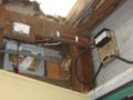
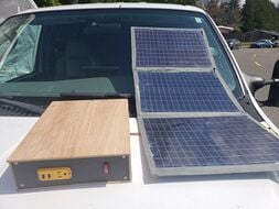
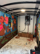
Fig 1:Existing system components
-
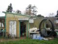
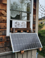
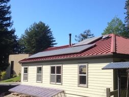
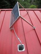
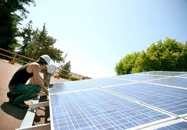
Fig 2:Existing solar panels on building at the AEF
-
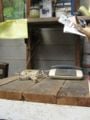
Fig 3. Old answering machine
-
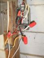
Fig 4. Old outlet for answering machine


Proposed Timeline[edit | edit source]
| Item | Proposed date | Date met? |
|---|---|---|
| Sizing of system and pricing components for client and CCAT approval | 3/11/08 | Yes! |
| Budget turned into CCAT | 3/12/08 | Yes! |
| Replace existing wiring with new wiring on photovoltaic system, install inverter, new battery and test | 3/29/08 | Yes! |
| Create user manual/maintenance log for system | 4/16/08 | Yes! |
Criteria[edit | edit source]
| Criteria | Constraint | Success? |
|---|---|---|
| Cost | Under $400 | Yes |
| Easily Maintained/Documentation | Easy to maintain by others and clearly documented. | Yes |
| Safe | Least chance of electric shock-no exposed wiring | Yes |
| Educational/Usable by all who are apart of AEF | Answering Machine works to provide easy access tool to the farm/shareholders | Yes |
| Durability | Lasts for many years, continuous educational tool | Yes |
Literature Review[edit | edit source]
There has been substantial discussion and writing on PV design, installation and maintenance. This system is not-grid connected so we focused on the same literature reviewed for our other project:
Engr 305 solar learning station which can be accessed here literature review and here Photovoltaics.
Components and their functions[edit | edit source]

- 1-Panel
- Collection of PV cells designed and installed on the panel depending on serial or parallel configuration
- 2-Absorbed Glass Mat (AGM) Sealed Battery
- Storage of DC Electrical Current.
- 3-Charge Controller/Low Voltage Disconnect (LVD)
- Regulates battery voltage and controls the charging rate, or the state of charge, for batteries. LVD shuts system off when voltage drops below 11.6 v and turns it back on after the battery has charged to 12.6 v.
- 4-Inverter
- Changes direct current (DC)generated by the Panel to alternating current (AC)used by households.
- Load (Answering Machine)
- Any electrical component within a circuit that draws power from that circuit.
- Most loads can be turned on and off, such as a light bulb or a refrigerator.
- Loads are either AC or DC.
- Fuses
- When a current exceeds a fuse´s rated amperage, the circuit opens and stops all current flow. When a fuse has "blown", it must be replaced.
- Meter
- A gauge that allows you to see from where you are pulling your power, and how much power is being drawn from the loads.
- 5-Outlet
- Outlet to run AC appliances-answering machine
Operating/Maintenance Instructions for components[edit | edit source]
- Answering Machine
- The answering machine is a used ATT 1715 and the user's manual is on-line
- Charge Controller/Low Voltage Disconnect
- The charge controller is a SunSaver 10 Amp Unit and the user's manual is on-line
- Inverter
- The Inverter is a Xantrex XPower Inverter 400 and the user's manual is on-line
System Installation[edit | edit source]
After assessing what components could be re-used from the old system and answering machine (Fig 1, 2, 3, 4), we got together to plan out the re-installation. Cody, being better at tough installation tasks, rebuilt the battery box (Fig 5), re-wired and attached the charge controller and inverter(Fig 7,8,and 9), and coached Bob as he re-wired the AC portion of the system. Bob ran Romex wiring from the inverter to the AC plug box. He also wired the AC outlet as it previously had direct DC wiring (Fig 4). Bob re-wired the compost fan to protect anyone from getting shocked if they fell asleep while on the toilet (Fig 13). We replaced all old wiring with new wiring and fastened with the existing hangers.
We were careful to have all components either covered from the elements or away from incidental human contact. This part was actually easier than the learning station as we could work at the same time instead of one at a time because of space. Once we were done and plugged in the new answering machine, it all worked perfectly and it looked good(Fig 10, 11, and 12)! For awhile...
System Installation Photos[edit | edit source]
-
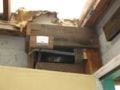
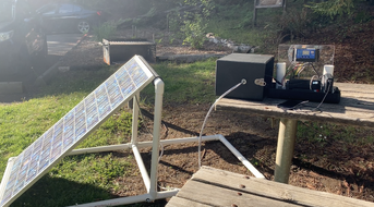
Fig 5. New battery box
-
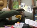
Fig 6. Bob installing new AC outlet for answering machine
-
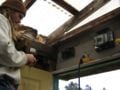
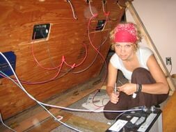
Fig 7. Cody wiring the charge controller
-

Fig 8. Wiring the new system. Team work!
-
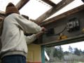
Fig 9. Hooking up the final wire to charge controller
-
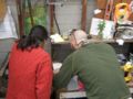
Fig 10. Sarah and Bob fine tuning the answering machine
-
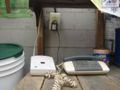
Fig 11. New answering machine and AC outlet
-
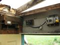
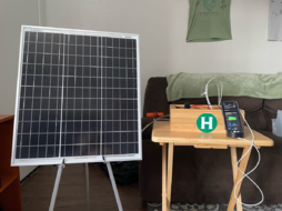
Fig 12. New system
-
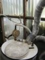
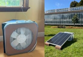
Fig 13. New wires for composting toilet fan


System Testing, Troubleshooting, Precautions and Maintenance[edit | edit source]
- For a project on the troubleshooting, repairing, testing and maintaining of this system visit AEF photovoltaic system/Troubleshooting
First we assessed the current system and figured out which components were still good and which ones were bad. The battery was five years old, would not hold a charge, and needed to be replaced. The charge controller still worked, but we decided to replace the old one with a new charge controller with a low voltage disconnect (LVD). This prevents the battery from being discharged to levels that decrease its life.
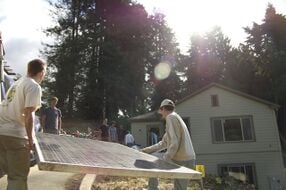
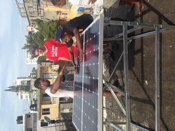
Using the old wiring coming from the solar panel, we tested the voltage coming from the panel to the charge controller. Only 1.79v were coming through so our initial thought was a bad panel. CCAT had some panels and were willing to donate one in case the original was bad. On a sunny day the panels in their Solar Trailer were all tested and one very similar to the existing panel was donated. But, it turned out that it was the old wiring. After removing the old wiring and testing the panel, it showed us 19.5v. The lifespan of a panel at full voltage is 15 - 25 years and after that the voltage output only slightly decreases.
After the system was completely installed, we tested the answering machine and everything worked. We were able to leave messages on the answering machine for a week before the system turned off. It now has been a full week and the system has not yet turned on, we tested our system at every point checking to make sure that our wiring was done correctly. The wiring was determined good and now we are testing individual components. The inverter worked when hooked up to battery, so now we're testing the battery to make sure it will hold a charge. All components are new so it is difficult to troubleshoot a new product being bad. After charging the battery up with a battery charger a load test was performed to make sure the voltage didn't drop rapidly. The battery was determined good, so now its down to the charge controller and/or the panel. With the battery charged we hooked it back up to the system and it worked again for a week. By bringing another battery in and hooking it up directly to the panel(around the charge controller), we were able to determine that the panel and wiring are good and eliminate them from scrutiny. We are investigating the charge controller. At this point its a matter of patience, time, and more trouble shooting if the problem persists.
List of steps to take when testing this system:
- Test system meters-Test on a device where you know the voltage and verify it is working and correct
- Array/panel voltage-Use a DC voltmeter/ampmeter to measure the voltage/amperage(in full sun) in an array/panel and record
- Battery voltage-carefully measure the voltage of the battery before and after connecting and record
- Check status indicators on charge controller and inverter if available
- Check all wiring to see if any is live by testing voltage and/or current at all points before and after a component
- Check all terminals and wires for loose, broken, corroded or burnt connections or components
- Make sure charge controller is clean
- Fire up the system under full sun and re-test each point and component for common voltage/amperage
- Turn on the answering machine!
Reference: Maintenance and operation of stand-alone Photovoltaic systems (1991). Sandia National Laboratories, Albuquerque, New Mexico 87185-5800 157
Troubleshooting Document For the AEF
This is an overview/basic troubleshooting document for many of the components of the AEF solar system including the answering machine.
- ANSWERING MACHINE
- If trouble occurs, turn off then back on. If problem persists, take home to try in different outlet. For programming, see enclosed user manual.
- CHARGE CONTROLLER
- For hook up and wiring instructions, please see enclosed diagram. For basic troubleshooting, test all three connection points with a voltmeter. If they are bad, it may need replacement. If they are good (have all the same voltage), the problem is most likely something else.
- BATTERY
- Check all points for corrosion and test each terminal with a voltmeter. If the voltage is below 12 volts and/or the Low Voltage Disconnect light is lit on the Charge Controller, unplug the answering machine and wait until you have two hours of full sun, then re-test. If not charging, the battery may be bad.
- INVERTER
- Using a voltmeter, test points on both sides of the inverter(one is AC and the other DC), during full sun if possible. For more troubleshooting, see the enclosed manual.
- PANEL
- Test panel by disconnecting from charge controller during full sun and using a voltmeter to test the voltage. It should be around 18 volts DC.
ALL COMPONENTS BUT THE BATTERY HAVE MANUALS ON-LINE AND ON-SITE.
Precautions
- Do not touch any of the wires with your hands or a metal tool when the system is connected.
- Read any material in our "how-to" packet before attempting to fix. The "how-to" packet has the components and diagrams above, a hard
- Only let someone that knows what they are doing repair or change the system or its wiring.
Maintenance
The following are maintenance logs for the AEF PV System and are recommended to be filled out monthly.
Budget[edit | edit source]
| Component | Cost |
|---|---|
| AGM 12 Volt 75 Amp Hour Battery | $160.95 |
| 400 Watt Inverter | $42.90 |
| Charge Controller with Low Voltage Disconnect | $69.95 |
| 15 Amp Fused Outlet | $13.50 |
| 24 feet of Romex wiring | $48.00 |
| 25 feet of 10 gauge wiring | $12.25 |
| 7 Feet of 12 gauge wiring | $2.45 |
| Answering Machine | $3.82 |
| Total | $353.82 |
Update October 2013[edit | edit source]
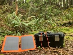
-

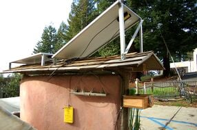
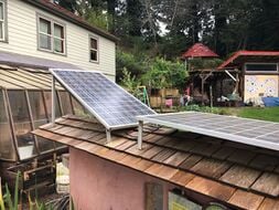
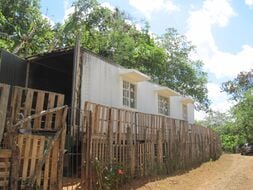
Figure 14
-
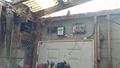
Figure 15

For an ENGR 308 class assignment, me and my partner Drew collected information on the Bayside Park Farm's projects listed on Appropedia and learned enough to update each project. After speaking with farmers Jayme and Leandra, we learned that the photovoltaic system still has all components hooked up (Fig 14&15), but is no longer in use. Since installed in April, 2008 the system was used to power the answering machine and a compost fan. Then was used to charge a battery for the solar water heater after it was installed in May, 2010. It was all working well, however, Leandra told me that it was not providing enough energy as they needed anymore and they became hooked up to the grid this last May 2013 when the solar water heater was dismantled and the new wash station was built. They are looking to see the arrays back in use soon as they served them well over the last ~5 years.