
The Solar DIY Air Filter designed by Radiant Enterprises is a project aimed at creating a design for an accessible, replicable air filter design that can be used in power-outage instances, and was designed during the Spring semester of 2022 at Cal Poly Humboldt. The motivation for this project was to create a design that would both be useful in emergency situations and impactful on a larger scale. The full technical design document can be found here.
Background[edit | edit source]
Appropedia is a website where thousands of users post sustainable design solutions for others to replicate. One of the main directives of Appropedia is, "to develop and share collaborative solutions in sustainability, poverty reduction and international development through the use of sound principles and appropriate technology, original research and project information."[1] Previously on Appropedia, there has not existed a design for an air filtration system that will work in emergency situations that result in a power outage. The foundation's Executive Director Emilio Velis took note of this issue and commissioned our team, Radiant Enterprises, to tackle this problem. Emilio is an engineer whose passion to help communities solve problems by implementing appropriate technologies is one of the driving forces behind his work at Appropedia. Radiant Enterprises is composed of 3 Cal Poly Humboldt environmental engineering students. Our members, Hudson Mierau, Joe Rosenquist, and Kyle Wolfe formed this team in Spring 2022 to tackle design challenges in the ENGR215 Introduction to Design course. Our project builds on the groundwork laid by a DIY air filter project developed by by Bikash Pradhan, Nicole Salas, Amin Younes for Engineering 535, Development Technology at Cal Poly Humboldt.[2] Their Appropedia page and design document are recommended reading for those who want more detailed information about the performance of the air filter design when connected to an uninterrupted power source.
Problem statement and criteria[edit | edit source]
The objective of Radiant Enterprises' design project is to create a replicable, solar-powered air filtration unit. A major objective was to make the instructions to build this design easily accessible through an Appropedia page. Materials used will be reasonably accessible worldwide or otherwise substitutable by other similar materials. The product itself should include a solar-charged battery, aiming for long-life efficiency, and a charge indicator. The Solar DIY Air Filter should be prioritized to tackle air-quality issues arising from natural disasters; however, it may be repurposed to filter indoor air to reduce pathogens such as those that cause COVID-19.
Criteria were created by the team with the approval of the client. Listed below are our criteria with definitions and importance on a scale of 1-10, with 1 being the least important and 10 being near essential.
Design Criteria
| Criteria | Weight | Description |
|---|---|---|
| Cost | 9 | The amount of money spent on the initial construction of the design. |
| Power Efficiency | 8 | The amount of particulate matter the device can remove from the air per kWh. |
| Ease of Assembly | 7 | How long it takes for a person at any given skill level to assemble a functional design. Also takes into account availability of materials (i.e. availability at local stores, shipping time and availability in online marketplaces). |
| Filtration Efficacy | 7 | The rate at which particulate matter is cleared from the air (in this case, PM 2.5). The metric is the Clean Air Delivery Rate (CADR) |
| Hours of Autonomy | 6 | How many hours the design can run independent of solar exposure (i.e. how long can the design run on a single charge of its battery) |
| Noise Level | 3 | The noise level in decibels (dB) produced while the design is active |
Prototyping[edit | edit source]
Fan Function Prototype[edit | edit source]
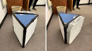
For our first round of prototyping, we decided to assemble the fan/filter unit of our design so we could see how easy it would be to assemble. Another objective of this prototype was to test the power draw of the fan itself. We found that this design would work well for our final product, so we continued to use it for the rest of our project with one additional modification: the fan shroud. The fan shroud increases the net directional airflow by reducing counterflow at the corners of the fan without increasing the power usage.[3] Depending on the model of fan used, the fan shroud can increase airflow efficiency by 38-47%.[4] A 15-inch diameter cutout shroud was used for our Lasko fan as it has been determined to be the optimal size. A guide for determining the size of a fan shroud can be found here.
-
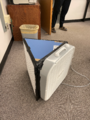
Prototype of DIY air filter
-
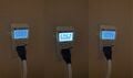
From left to right: power draw from the DIY air filter in watts on low, medium, and high speed.
-
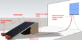
![From top to bottom: crude prototype of the electrical component layout with the DIY air filter [1], inverter [2], charge controller [3], solar panel [4], and battery [5]](/w/images/thumb/5/54/Component_Layout_Prototype.png/120px-Component_Layout_Prototype.png)
From top to bottom: crude prototype of the electrical component layout with the DIY air filter [1], inverter [2], charge controller [3], solar panel [4], and battery [5]


![From top to bottom: crude prototype of the electrical component layout with the DIY air filter [1], inverter [2], charge controller [3], solar panel [4], and battery [5]](/File:Component_Layout_Prototype.png)
Electrical Components Layout Prototype[edit | edit source]
Moving forward, we wanted to prototype the assembly of our electrical components. This was done with scrap material like small boxes, cloth, tape, and other miscellaneous materials to represent each electrical component. We found that with the proper instructions, this wiring would be relatively straightforward for anyone to replicate.
Description of Final Product[edit | edit source]
The final design was simply named the Solar DIY Air Filter. It consists of two apparatuses: one with the fan and filters assembled into an air filter and one housing the electrical components. The electrical components, including the solar panel, battery, charge controller, and inverter, are stored outside, and an extension cord brings power to the air filter apparatus inside the building. An electronic appliance timer is rigged to turn the fan on and off at set intervals to keep the room filtered while also conserving energy.
-
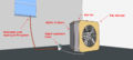
CAD of Electrical Components for Solar Module Portion of Design
-
3D CAD of Indoor Air Filtration Portion of Design
-
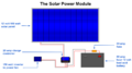
3D CAD of Solar Power Module Portion of the Design


Results[edit | edit source]
Two tests were conducted to measure the success of our design. The first test measured the hours of autonomy of the system running off power entirely supplied by the battery. Starting with the battery fully charged at 13.0 V, the fan was run on its lowest speed and the appliance timer duty cycle was set to 1/4 (1 minute on, 3 minutes off.) Under these conditions, system lasted for 27.6 hours before disconnecting at the 11.5 V low voltage disconnect.
The second test measured the recharge time using the solar panel and no load. During 8 hours of scattered sun and clouds, the battery increased in voltage by 0.8 V which would give it enough energy to power the system autonomously for an additional 24 hours. Had the load been connected during this charge time, it could have run continuously and still had enough charge on the battery to last another 16 hours without sun. Given these results, the design should theoretically be able to run continuously with no interruptions. However, the amount of sunlight during a charging period is the largest variable that can impact the status of the system, so periods of time during the day with very little sunlight due to weather could cause downtime in the operation of the air filter.
Although the filtration efficacy of the filter was not measured directly, we simulated the indoor air quality with the filter running using this Excel model created by Dr. Peter Alstone, Elizabeth Odell, Malcolm Moncheur, and Tanya Garcia with the Schatz Energy Research Center at Cal Poly Humboldt..[5] The parameters used were as follows. A room size of 220 square feet with an 8 foot ceiling (1760 cubic feet) which is the size of a master bedroom. An outdoor air PM2.5 concentration of 250 micrograms per cubic meter, which is rated as very unhealthy by the U.S. EPA.[6] The air infiltration exchange rate was set to 0.8 air exchanges per hour, which represents a relatively well sealed room. The air filter flow rate used was 300 CFM, which represents the average flow rate for the fan on low (1200 CFM) with a 1/4 duty cycle. Finally, the filter efficiency was set to a value of 50%. While MERV 13 filters should theoretically filter 90+% of particles the size of smoke particulate matter, the low velocity of air that DIY filters facilitate results in a drop in efficiency to between 48-67%.[7] These parameters resulted in an average indoor air PM2.5 concentration of 32 micrograms per cubic meter, shown visually in the graph below. This concentration corresponds to a moderate AQI which is associated with the following recommendation by the U.S. EPA: "Unusually sensitive people should consider reducing prolonged or heavy exertion".[6]

Construction[edit | edit source]
Materials[edit | edit source]
Components used in design
| Component | No. of parts |
|---|---|
| 55 Ah Deep Cycle AGM 12 V Lead Acid Battery | 1 |
| Ring Terminals | 2 |
| 14 AWG Wire (20 ft) | 1 |
| 14 AWG Butt Terminal | 1 |
| 20 A ATC Fuse | 1 |
| ATC Fuse Holder | 1 |
| Trickle Charger | 1 |
| 100 W Solar Panel | 1 |
| Solar Panel MC4 Connector Set | 1 |
| 20A Solar Charge Controller | 1 |
| 150 W Inverter | 1 |
| Extension Cord | 1 |
| Digital Appliance Timer | 1 |
| Box Fan | 1 |
| 20x20x1 inch MERV-13 Air Filters | 2 |
| Gorilla Tape Roll | 1 |
| Cardboard From Fan and Filter Boxes | 3 |
The assembly of this design also requires a handful of tools, including a wire stripper/cutter/crimping tool, the tools required to cut the chosen body material (in our case, scissors or a box cutter for cardboard), a yardstick or other measuring tool/straight edge, and a pencil or pen. A multi-meter is useful for troubleshooting connections while setting up the electrical components.
Building Instructions[edit | edit source]
Instructions on how to build the DIY air filter portion of this design are are provided below as both a video guide and written instructions. For more detailed instructions, see DIY air filter project.

Place the fan face-down (such that the portion that blows air is face down) on a flat surface. Align the bottom edge of one filter with the bottom edge of the fan and the side edge of the filter with the right side of the fan. Place two temporary pieces of tape down to keep the filter in place, but that are removable if necessary. Lift this filter up and repeat the process with the second filter, aligning the bottom with the bottom of the fan and the side with the left side of the fan

Rotate both filters up and align their untaped sides near the center of the fan. Tape this joint with another two pieces of temporary tape

Carefully place the fan-filter combo onto a large piece of cardboard and trace around the bottom of the filters. It is only necessary to trace the outline of the filters as the cardboard does not need to extend underneath the fan. Trace to the frontmost edge of the filters, then stop. Carefully move the fan and filters and use a straight edge to connect the endpoints of the trace. This piece will be used to seal the bottom of the unit. Cut this piece out, then trace and cut out an identical copy to be used for the top. In both cases, cut out a bigger piece than you think is needed, as the piece can always be reduced later.

Carefully place the fan upside down so that the bottom piece of cardboard can be attached. Line up all three edges of the cardboard triangle to the edges of the filters and fan as best as possible. If any areas extend too far beyond the edges of the filters or fan, carefully trim this excess. Then, as seen in the photo, attach this piece to the filters. Use small pieces of tape first to hold everything in place, then go over with one or two longer strips of tape. Note that in all instances of sealing with tape, it is recommended to make the seals as airtight as possible to maximize the efficiency of the filter. Note also near the top of the figure that the fan cord, which attaches to the back of the fan, is routed between the fan and the cardboard base. This will be properly sealed later.

Flipping the fan over, the cardboard top can now be attached to the top of the fan in a similar fashion. This piece should line up with the edges of the filters and backside of the fan. Since the filters are shorter than the fan, the cardboard will sit below the height of the fan, which is okay. This will be sealed later. For now, seal the cardboard top with the two filters and properly seal the joint between the two filters.

With the round shape of the fan on the square edges of the filters, there will be gaps in the sealing of the unit at each of the corners. To seal these, lay the unit facedown onto a piece of scrap cardboard, tracing along its curve. Make sure that there is enough thickness between the trace and the edges of the cardboard to fully seal these corners (a few inches should be enough; always leave more than you think you need and trim down to match later). The image shows this tracing. Cut this piece out and trace 3 similar pieces for the 3 other corners.

After trimming the piece down to better match the gap it is filling, it should fit around the corner of the fan. Note that the cardboard will not be flush with the air filter behind it, as the air filter is at an angle. Trim this edge to be close in width to the extent at which the filter behind it sticks out.

This piece is mounted in place with tape. Note that multiple pieces of tape are used to ensure the seal is as airtight as possible, as taping around a curved edge is more difficult with a single piece of tape. Repeat this with the other three corner pieces. With this step completed, look over the unit and ensure that every connection between two components is sealed. This may include the connections between the fan and the cardboard top/bottom and the left and right side of the fan with each filter. If any breaks in the seal arise, seal them with additional tape.

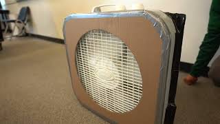
The shroud can be assembled using any remaining cardboard from the packaging on the box fan. Measure out the cutout diameter based on the brand of box fan (15-inch diameter for Lasko, 14.5 for Utilitech) leaving enough room on the sides to completely cover the face of the fan. Mark the center and create guidelines by measuring from the center to the radius.

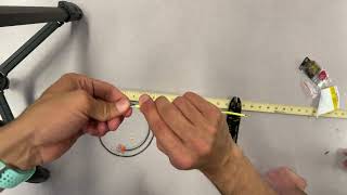
If a compass is available, use it to create a circular marking from the center to the guidelines. If not, simply pin a flexible length of material like a string or wire or the center marking, hold a pen at the end against the guideline, and rotate about the center.

Use the circular marking to carefully score and puncture the circumference with a knife or the point of a pair of scissors.

This scored cardboard can now be easily cut along the perforations. Remove the circular center and trim the edges to fit to the face of the box fan.

Finally, tape the shroud to the box fan around the edges of the cardboard
Instructions on how to wire the electrical components for the solar power system are provided below as both a video guide and written instructions.

This portion of the assembly is more prone to error than the last, so follow instructions carefully. These instructions are as follows. Cut two feet of 14 gauge wire and strip it at the ends.

Insert a 20 amp fuse into the fuse holder as shown. Notice that the wire of the fuse holder is already stripped. It may be necessary to strip additional wire later.

Attach these wires together with a wire connector. Ideally the fuse should be as close to the battery as possible, so if there is a noticeably longer end of the fuse holder, connect that end to the wire. Then, crimp a ring connector onto the shorter end of the fuse holder as shown.

Cut another two-foot section of 14 gauge wire and strip both ends. Attach a second ring terminal to one end. Then, attach these wires to the battery as shown in Figure 18. The wire with the fuse attaches to the positive terminal of the battery and the wire without a fuse attaches to the negative terminal. Be careful not to touch the ends of these wires to each other, or to touch any conductive material between the two or between the terminals, as this will short the battery and could injure the user or potentially start a fire.

Locate the positive and negative battery ports on the charge controller. Connect the positive wire to the positive terminal and the negative wire to the negative terminal. If this is done correctly, and if the battery is charged, the charge controller should turn on as shown.

To connect the panel to the charge controller, strip a pair of properly sized wires on both ends (we used 3ft in each direction of 14 AWG) and locate a male and female MC4 connector. Within the connector kit, locate the connector pins. The larger of the two pins is the female pin that will fit into the male MC4 connector, while the smaller of the two pins is the male pin that will fit into the female MC4 connector. The images show the MC4 connectors and their corresponding pins

Slide the pins onto the stripped wires and crimp the ends. This task can be slightly challenging without a ratcheting crimp. Slowly work around the outer edges at the bottom until the connection is secure enough that it resists when you pull it and does not slide off the wire. As with all connections, check the conductivity before proceeding.

Disassemble the MC4 connector by unscrewing the top. Feed the crimped wire and pin through the unscrewed top of the connector, then insert the pin into the bottom of the MC4 connector. There should be an audible click when a connection between the pin and MC4 connector has been establised. Screw back on the top of the connector.

The wires joined to MC4 connectors can now be joined to the solar panel's MC4 connectors. Male to female, female to male. Note which panel's connector is positive, and which is negative. The male MC4 connector on the panel is usually positive. Connect the stripped ends of the wires (opposite to MC4 connection) to the charge controller's corresponding positive and negative terminals.

The inverter likely comes with two sets of wires: one with clip connectors and one with a male cigarette lighter plug. Both should have ring terminals on the end. Trim either the cigarette plug or the clips from the wire, depending on which will be implemented into the design (we opted to trim the cigarette plug). To do this, open up the cigarette plug and detatch the wires from any components such as springs, fuses, and ground terminals.

Separate the wire a bit and strip enough from each wire to connect it to the load terminals on the charge controller. Take note of which wire leads to which ring, and make sure that the wire connected to the positive terminal of the charge controller is connected to the positive terminal of the inverter and the negative terminal of the charge controller is wired to the negative terminal of the inverter. If everything has been wired correctly thus far, the inverter should power on.
Cost of Materials[edit | edit source]
Table of Costs
| Component | Cost per Unit ($) | Amount | Total ($) |
|---|---|---|---|
| 55 Ah Deep Cycle AGM 12 V Lead Acid Battery | 124.76 | 1 | 124.76 |
| Ring Terminals (2 pack) | 4.29 | 1 | 4.29 |
| 14 AWG Wire | 0.96 | 20 feet | 19.20 |
| 14 AWG Butt Terminal | 0.10 | 1 | 0.10 |
| 20 A ATC Fuse (10-pack) | 8.59 | 1 | 8.59 |
| ATC Fuse Holder | 5.36 | 1 | 5.36 |
| Trickle Charger | 10.84 | 1 | 10.84 |
| 100 W Solar Panel | 93.30 | 1 | 93.30 |
| MC4 Solar Panel Connectors (6 pack) | 9.75 | 1 | 9.75 |
| 20 A Solar Charge Controller | 16.26 | 1 | 16.26 |
| 150 W Inverter | 16.26 | 1 | 16.26 |
| Extension Cord | ~ | ~ | ~ |
| Digital Appliance Timer | 15.45 | 1 | 15.45 |
| 20" Box Fan | 35.79 | 1 | 35.79 |
| 20x20x1" Merv 13 Furnace Filter | 26.97 | 2 | 53.95 |
| Carboard | 0 | N/A | 0 |
| Total Cost ($) | 413.9 | ||
Operation[edit | edit source]
Instructions on how to set up the solar power system and operate the DIY air filter are provided below as both a video guide and written instructions.
Use[edit | edit source]
During times where the building being filtered has electrical power, the air filter unit can simply be plugged into the wall and run constantly. Additionally, keep the 12 V battery connected to the trickle charger and plugged into a wall outlet when electrical power is available. For instances where electrical power is not available, use the solar panel and other electrical components to power the air filter unit. Below are the steps to set up and run this unit off of solar power.
Find a location outside where the panel will receive plenty of sunlight during the day. Determine the optimal angle at which the panel will be most perpendicular to the sun; this is dependent on the latitude it is placed at and the time of year. Assuming that the panel is to be set up for use during the summer at a latitude of 30° North, facing the panel Southward at an angle of 15° will yield optimal energy production for the summer months. At any latitude X°, the optimal summer angle will be at (X - 15)°. For panels in the northern hemisphere, they will face southward and vice versa. The equation sin(θ)×P=H can be used to solve for the height H at which the solar panel of length P will need to be placed in order to match the desired angle θ.
The rest of the components should be carefully stationed nearby. We recommend storing the battery, charge controller, and inverter underneath the solar panel in a container. Plug an extension cord into the inverter and then run it into the desired building through a cracked door or window. Seal up as much of the cracked door or window as possible with spare clothes, rags or duct tape to prevent as much particulate matter from entering the building as possible. Depending on where the solar panel is set up, multiple or longer extension cords may be needed.
Run the extension cord to the desired placement for the air filter unit. Plug the appliance timer into the extension cord, then plug the extension cord into the filter apparatus. Set the timer to run for the desired duty cycle (our tests used 1/4 cycle, 1 minute on 3 minutes off); this way, the device can efficiently run only for the fraction of time necessary to keep the particulate matter concentration below dangerous levels. To determine an appropriate duty cycle for your parameters, use this Excel model developed by Alstone et al..[5] Enter your room size and a value betweem 0.5 and 1.0 for the infiltartion air exchanges per hour. 0.5 represents a near perfectly sealed room, while 1.0 represents a very poorly sealed space. Next set a filter efficiency of 50%. Vary the filtration flow rate until the average indoor air concentration is at a desirable level. Divide this model flow rate by your fan's flow rate at a given setting to yield the duty cycle. This is the duty cycle that you will then set on your appliance timer for the air filter.
Maintenance[edit | edit source]
The frequency with which the filters will need to be replaced will vary depending on how often the device is used, what speed the fan is run at, and the quality of air that the DIY air filter is filtering. Most filter manufacturers advise replacing filters every 3 months, including 3M, the manufacturer of the Filtrete 2200 MERV 13 filters in this design (Filtrete 2022). However, this assumes the filters are used in a high airflow HVAC environment with constant usage. Some air quality experts believe that multiple filter box fan units can last for much longer, 5 to 6 months[8] or even up to a year.[9] When filters have become clogged with particulate matter, they will need to be replaced with fresh filters, incurring a cost of $53.95 every 5 months to a year.
Next Steps[edit | edit source]
Modifications to be Implemented[edit | edit source]
For a number of reasons, it may be desirable to interchange certain components of this design with more effective alternatives. This section details what is required in order to change certain components of the design.
Upgrading Battery Storage[edit | edit source]
The easiest way to upgrade battery storage is to purchase multiple lead acid batteries and to run them parallel to each other. Running batteries in parallel adds up their total storage capacity; for instance, if we were to purchase and run parallel a second 55 Ah battery, we would have 110 Ah total. Considering that lead acid batteries may only be discharged 50% without damaging them, this would mean that only 55 Ah are available for use, but this still doubles the battery capacity that we currently have.
Alternatively, a lead acid battery could be swapped for a battery with a higher depth of discharge. A single 35 Ah lithium iron phosphate (LiPO4) battery, for instance, would be able to discharge at least 80%, meaning at least 28 Ah available from a single battery compared to the 27.5 usable Ah from the lead acid battery we chose. Lithium iron phosphate batteries offer multiple advantages, the largest among them being their weight. Due to LiPO4's much higher energy density, an equivalent capacity battery can be used at 1/5th of the weight. LiPO4 batteries would also provide 10x the cycle life, requiring less maintenance costs incurred in replacing the battery.[10] The downside to using a LiPO4 battery is that a different charge controller than the one used in our current design would be needed, as ours is only rated to be used with lead acid batteries.
Upgrading PV Output[edit | edit source]
Energy output from the solar panel can be easily upgraded in two ways: by purchasing a larger panel or by running multiple panels in parallel, similarly to the batteries. The complications from this are again related to the charge controller. Our charge controller is rated at 20A, and dividing by a general safety factor of 1.25 allows for a PV array of 16A to safely operate with this charge controller. Our 100W panel is rated to output a short-circuit current of 6.5A, which is comfortably within this safe value, but any PV array that goes over this value will need a charge controller appropriately sized for it. If more powerful panels are purchased, check their manufacturer-specified short-circuit current, and if multiple panels are run in parallel, add up their total short-circuit current. Multiply this by the safety factor 1.25 and use this value to research a charge controller that can handle this level of current. Also be sure to check the open circuit voltage of any panel besides the one used in this design and ensure that it does not exceed the voltage rating of the charge controller.
Corsi-Rosenthal Design[edit | edit source]
One of our considered designs followed the Corsi-Rosenthal Design,[11] which included an additional two air filters in the body of the filter itself. We did not follow this design in our final solution, as it would put us over-budget on an already efficient air filter. This design already exists, and our designed filter would simply need to be replaced with this one.
Modifications to be Designed[edit | edit source]
There are a handful of other modifications we had in mind while creating this design, however due to time/budget constraints we could not fully explore them. Below will be brief descriptions of these ideas.
Storing Electrical Components Inside[edit | edit source]
With the properly sized wire, it should be possible to store the battery, charge controller, and inverter inside. This would reduce the risk of components being mistaken for toys by children outside, damage from sun exposure, or possible theft if left unattended in a front yard. This would involve replacing the 14 AWG wire between the panel and the charge controller with a thicker gauge depending on the distance from the panel to the charge controller. We were unable to follow through with this concept because we could not budget for a long length of thick wire; however, when making your own design, you may wish to make this modification.
Using an ampacity chart such as the one found in To Catch the Sun, this thickness can be determined.[12] Measure the distance from the solar panel to the charge controller, then double it to determine the round trip length. This chart will account for round trip lengths up to 90 feet, but others available online will account for further lengths. Then, divide the panel's power rating (100 Watts) by the panel's open-circuit voltage (21.6 Volts). Our panel outputs roughly 4.6 Amps by this calculation; rounding up to 5 amps determines the minimum current to size for, and rounding up to 10 Amps will ensure safety in case the panel overproduces.

One thing to consider when making this change, however, is that large wire will not fit in our charge controller's ports. A potential solution would be to reduce the thickness of the wire at the connection to the charge controller, but we have not tested this and cannot confirm that it is a safe thing to do. One could also purchase a different charge controller designed for thicker wire, but this would likely add to the cost.
Monitoring Air Quality[edit | edit source]
One of the challenges we faced while developing our design was how to regulate the power such that the filter would only run when it needed to in order to maintain a safe air quality. We tackled this issue with a digital appliance timer, calculating the amount of time the filter would need to run under set conditions to maintain a healthy air quality.
An alternative solution we thought of would be to use an air quality monitor and an Arduino micro-controller to turn the fan on when the indoor air quality reached a certain threshold. We concluded that this design would be inaccessible to a wider audience unfamiliar with micro-controllers. If it is desirable to tie the filter usage directly to air quality, this route should be further explored for further iterations of this design.
Update June 2022[edit | edit source]
This design won the Spring 2022 3D CAD competition hosted by SolidProfessor.
References[edit | edit source]
- ↑ Aaron Antrim, Kathy Nativi, Chris Watkins, Lonny Grafman, Emilio Velis, Sofía Aparicio (2006). "Appropedia:About". Appropedia. Retrieved April 21, 2022.
- ↑ Bikash Pradhan, Nicole Salas, Amin Younes (2021). "535 FiltAirs DIY air filter". Appropedia. Retrieved April 18, 2022.
- ↑ Jim Rosenthal (2020). "How to Improve the Efficiency of the Corsi-Rosenthal Box Air Cleaner". Tex-Air Filters. Retrieved May 7, 2022.
- ↑ "How to build the shroud". Clean Air Crew. Retrieved May 7, 2022.
- ↑ 5.0 5.1 Peter Alstone, Elizabeth Odell, Malcolm Moncheur, and Tanya Garcia. "Air Quality 'Box Model' Spreadsheet". Schatz Energy Research Center. Retrieved May 6, 2022.
- ↑ 6.0 6.1 AirNow.gov. "AQI Calculator". U.S. EPA. Retrieved May 6, 2022.
- ↑ Rachael Dal Porto, Monet N. Kunz, Theresa Pistochini, Richard L. Corsi, and Christopher D. Cappa (2022). "Characterizing the performance of a do-it-yourself (DIY) box fan air filter". Aerosol Science and Technology Retrieved May 6, 2022.
- ↑ UC Davis (2022). "The Corsi-Rosenthal Box: DIY Box Fan Air Filter for COVID-19 and Wildfire Smoke". Western Center for Agricultural Health and Safety. Retrieved April 20, 2022.
- ↑ Danny Elfstrom (2021). "How often should I change the filter? It depends on the air it's filtering (forest fire smoke?) and run time. Suggest once every three months for this single-filter design. A Corsi-Rosenthal box made from four or five filters might last a whole year". Twitter. Retrieved April 20, 2022.
- ↑ Eco-Worthy (2022). "LiFePO4 12V 10Ah 20Ah 30Ah Lithium Iron Phosphate Battery". Eco-Worthy. Retrieved May 5, 2022.
- ↑ Clean Air Crew (2021). "DIY box fan air filters – Corsi-Rosenthal box". CleanAirCrew.org. Retrieved May 5, 2022.
- ↑ Lonny Grafman, Joshua M. Pearce (2020). "To Catch the Sun". Humboldt State University Press. Retrieved May 6, 2022.