
Waste plastic extruder: Files
Return to Waste plastic extruder.
Parts files
[edit | edit source]Main body
[edit | edit source]Manufacturing diagrams will be added below for components of the waste plastic extruder.
Drawings included below are:
- main body assembly drawing
- hopper
- flange
- die
- gear pipe section
- hopper pipe section
- heating pipe section
For this particular extruder, each of these components were fabricated using steel.
-
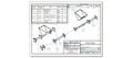 Figure 1: Assembly diagram of main body including parts list. Part diagrams included below
 -
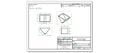 Figure 2: Hopper as constructed for waste plastic extruder. Dimensions can be easily modified as needed.
 -
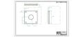 Figure 3: Flange - used to connect various pipe sections together and attach die. Connected with fasteners.
 -
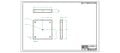 Figure 4: Die used to extruder 3mm filament for use with RepRap.
 -
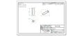 Figure 5: Gearing section of pipe. Welded to flanges.
 -
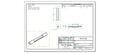 Figure 6: Hopper section of pipe. Welded to flanges.
 -
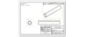 Figure 7:Heating section of pipe. Welded to flanges.


]
Shaft Addition: <gallery> Image:Shaft addition WPE.jpg|Shaft extension <gallery>
| Authors | |
|---|---|
| License | CC-BY-SA-3.0 |
| Cite as | "Waste plastic extruder: Files". Appropedia. 2011–2025. Retrieved July 9, 2026. |