This document presents the comprehensive final course project undertaken during the Spring 2023 semester for ENGR 535 (Development Technology), a graduate course at Cal Poly Humboldt. Student team collaborated with the Schatz Energy Research Center to develop air quality monitoring technology to deploy in remote, wildfire-affected areas. The objective assigned to our team was to successfully ideate, design, prototype, construct, and test a solar-powered air quality monitoring system for use in off-grid homes. The deployment of this project is expected to take place in Orleans, situated in Humboldt County, CA.
This page contains our final product design, construction manual with video and user manual as well as complete instructions and suggestions for appropriate usage.
Our criteria and constraints for this project are based on our best understanding of the stated needs of our client. The most important criteria for this system are reliability, durability, and ease of transport. This system must collect PM2.5 data reliably and as consistently as possible. It must be resilient to wildlife and moderately resilient to weather. Finally, it must be relatively easy to collapse and transport in the trunk of a car. The final design will be thoroughly assessed using a series of tests to determine fit to the criteria outlined by the team. The testing and results section of this report will provide information on how the system fits the criteria.
Table 1. Criteria and Constraints
Criteria
Constraints
Weight
Reliability
Sizing: the system must run 24/7/365.
Connectivity: must be able to collect PM2.5 data without significant interruptions.
10
Durability
Must be resistant to wildlife, weather, and other external influences.
9
Ease of Transport
Must be relatively easy to transport from place to place in a car.
8.5
Ease of Use
The construction and user manuals must be clear and easy to use.
The system must be easy to use.
8
Safety
System must not be a hazard to users during construction or use.
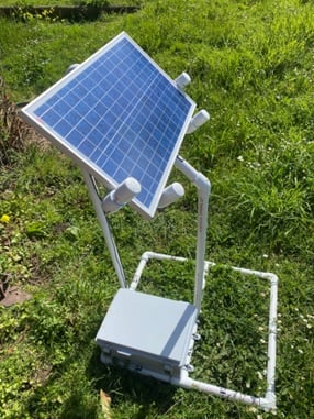
The final design for this project consists of a 30W panel, a 128Wh battery, a 30A charge controller, a DC-DC Buck converter, the Purple Air sensor, and a PVC mounting structure. This system is expected to successfully power the Purple Air sensor 24 hours a day, 7 days a week, and 365 days a year, with expected days of autonomy of approximately 3 days. The physical system is constructed using schedule 40 1” PVC pipe and fittings, assembled using PVC cement. The final system includes a 14.6"×10.6"×5.9" junction box which holds the battery, charge controller, buck converter, and other moisture-sensitive wiring.
A 3-foot USB to micro-USB cord is connected to the charge controller to power the Purple Air sensor. Both the micro-USB and the PV wires inside the junction box are fed through a PG7 cable gland. Additionally, a set of 16 1.5” galvanized metal U-pins serve to stake the base into the ground to ensure structural integrity. Any loose wires are fastened taunt to the PVC mounting structure using high-quality, outdoor-grade zip-ties. Zip-ties are also used to fasten the junction box and PV panels to the PVC frame. A complete list of materials and cost breakdown is provided below.
Ensure that both pipe and fittings are clean and free of dust, dirt, excessive moisture, or any other debris. Use a cloth to clean as needed.
Before beginning, keep in mind that PVC glue dries up quickly. Read through the instructions carefully before joining your first pipe and fitting.
Use the dauber brush attached to the PVC glue container lid to apply a generous layer of glue to the inside of the fitting, without allowing it to puddle or drip, and to the outside of the pipe end, as shown in the images below:
Quickly, insert the pipe end into the fitting, twisting the pipe one-quarter turn.
Hold the pipe into the fitting for 30 seconds and allow it to dry.
The standalone Purple Air sensor is a device that measures and reports real-time air quality to the Purple Air sensor’s website. This system uses a solar panel, charge controller, and battery to power the Purple Air sensor. The purpose of the user manual is as follows:
Provide instructions to install, operate and maintain the standalone air quality monitoring system.
To understand the critical safety features and the system's technical specifications.
Ensure the area has access to sunlight(south-facing) and is not blocked by trees, structures, or other objects before installing the device.
Ensure that the system is installed at a place free from nearby pollutant sources (don’t install near a garage, a gravel road, a fire pit, smoking areas, building exhaust, etc.). Pollutants such as vehicle exhaust, dust from gravel roads, and smoke from fire pits can negatively impact the air quality in the system's installed area. It is recommended to install the system at least 50 feet away from any potential pollutant sources mentioned above.
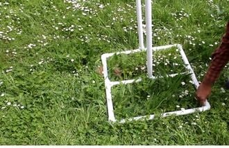
Fig 1. PVC mounting structure placed on the ground.Place the constructed PVC mounting structure on the ground considering the conditions stated in 1 & 2 above, as shown in Fig 1.
Fig 2. Fixing 1.5” galvanized U pinsFix the 1.5” galvanized U pins across the base of the PVC mounting structure as shown in Fig 2.
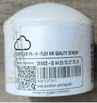
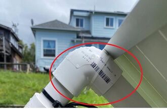
Fig 3. Picture of the device id of the Purple Air sensorTake a picture of the device id of the Purple Air sensor, as this would be needed for registration, as shown in Fig 3.
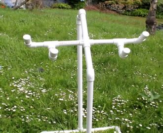
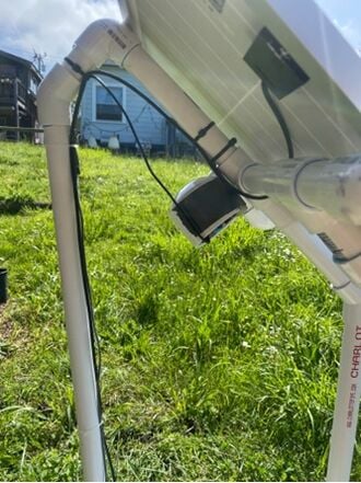
Fig 4. Purple Air sensor placed in the middle of the top section using a zip tie.Place the Purple Air sensor in the middle of the top of the mounting structure with the help of zip ties, as shown in Fig 4.
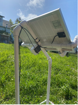
Fig 5. Solar PV module mounted on the PVC mounting structurePlace the Solar PV module (30 watts) at the top of the mounting structure, as shown in Fig 5.
Fig 6. Solar PV module fastened with mounting structure using zip ties.Fasten the solar PV module using zip ties, as shown in Fig 6.
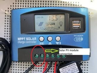
Fig 7. Connecting solar PV module to the charge controller.Take the wires from the PV module and the micro USB cable through the PG7 cable connector of the junction box. Connect the red wire from the solar panel to the + terminal and the black wire from the solar panel to the -ve terminal of the charge controller, as shown in Fig 7.
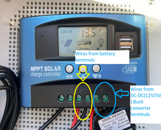
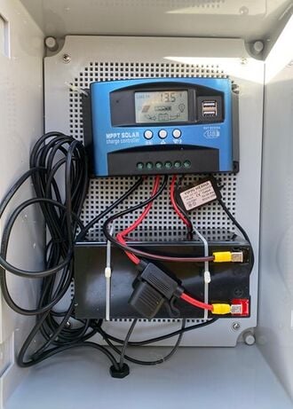
Fig 8. Connecting battery wires and DC-DC buck converter to charge controllerConnect the red wire having a 5A fuse and the black wire to the + and -ve terminal of the charge controller meant for the battery and connect the DC-DC buck converter to the Charge controller “load” terminals as per the polarity( red to the + terminal and black to the -ve terminal) as shown in Fig 8.
Fig 9. Placing the battery and charge controller inside the junction boxPlace the battery(vertically) and charge controller on the mesh of the junction box using zip ties and place the mesh in the junction box, as shown in Fig 9. Tighten the screws in the junction box.
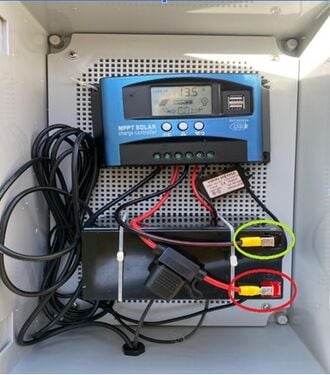
Fig 10. Connecting the battery to the charge controllerConnect the battery wires from the charge controller to the battery terminal, as shown in Fig 10.
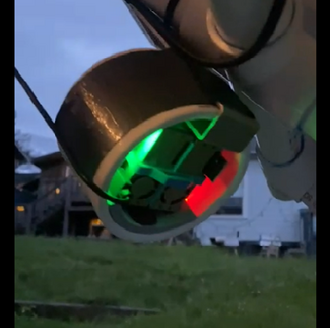
Fig 11. Connecting the micro USB cable to the micro USB port of the Purple Air sensorConnect the micro USB cable to the micro USB port of the Purple Air sensor, as shown in Fig 11. Check for the red LED; it shows that the Purple Air sensor is ON.
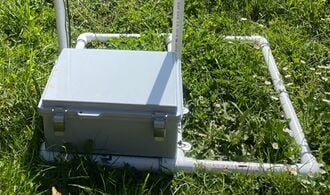
Fig 12. Fixing the junction box to the base of the mounting structureAdjust the wire length and close the junction box and place it on the base of the PVC mounting structure, and, using zip ties, fasten it to the base of the structure, as shown in Fig 12.
Fig 13. Fastening the wires to the mounting structure using zip ties.Fasten the wires from the solar PV module and the micro USB cable to the mounting structure using zip ties, as shown in Fig13.
Note: The user may use a USB-micro USB cable plugging the USB cable into the USB output of the charge controller and the micro USB to the Purple Air sensor by using a PG 13.5 or the higher cable connector. We have used a DC-DC buck converter(12V/5V) as we don't have the PG 13.5 cable connectors.
Ensure that the LEDs of the Purple Air sensor are ON, as shown in Fig 11.
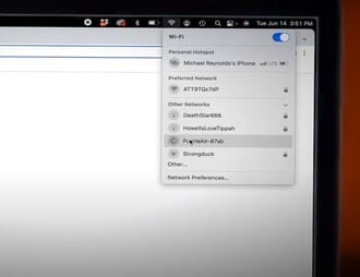
Fig 14. Purple Air sensor hotspotConnect to the sensor's hotspot by opening the network settings on your Wi Fi-capable device (phone, computer, etc.). The hotspot's name will be Purple Air-****, as shown in Figure 14.
A popup can show up depending on the Wi Fi-capable device being used. Open a web browser and type "http://192.168.4.1/config" into the address bar if it still does not display. Try momentarily stopping or disabling mobile data on your Wi Fi-enabled device and retyping the URL above if it still does not appear.
If the hotspot doesn't appear on a Wi Fi capable device, wait for 10 minutes and try again, as it may take a while for the Purple Air sensor network to appear.
If the sensor's Purple Air-**** network is not visible even after 10 minutes of power on, it may already be Wi-Fi-configured.
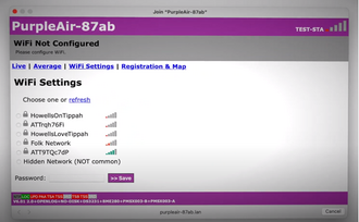
Fig 15. Connecting the Purple Air sensor to an available Wi Fi networkIn the popup window or http://192.168.4.1/config page, from the list of accessible networks, choose the one to which you are attaching your sensor. Input the Wi Fi network's password after that and select "Save," as seen in Figure 15. It may take a while for the connection to be established. “Looking Good” will appear at the top of the page after the Wi Fi is established.
Go to www.purpleair.com/register to register your Purple Air device.
First, type in your device-id from the picture you have taken, as shown in installation steps A-5.
Type in the email associated with the purchase of the device.
Select whether the device is located inside or outside.
Name the location where the device is currently located. (like, 879 Union Street).
Select Visibility: public (everyone).
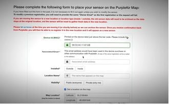
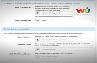
Fig 16. Device id, associated email address, location and its name for registrationSet the device's current location by moving the red indicator bubble on the map or typing in the location's coordinates as shown in Fig 16.
Skip the Onboard LED Options and Data Processor sections.
Fig 17. Owner name and email information to be filled for registrationFill in the Device Owner’s Information section with the necessary information as shown in Fig 17.
Agree to the terms and conditions and click on
2. Check whether the Purple Air sensor is visible at https://map.purpleair.com.
0–50(Green): The air quality is acceptable, and after 24 hours of exposure, there is little to no risk from air pollution.
51–100(Yellow): Acceptable air quality. Some individuals, particularly those with an abnormally high sensitivity to air pollution, may be at risk after 24 hours of exposure.
101–150(Orange): After 24 hours of exposure, members of vulnerable populations may develop health impacts. It is less likely that the general population will be impacted.
151-200(Red): After 24 hours of exposure, certain members of the general public may experience health consequences; people in vulnerable groups may have more severe health impacts.
201-300(Purple): Health warning: After 24 hours of exposure, everyone is at higher risk for health consequences.
>300(Maroon): According to the health warning for emergency conditions, everyone is more susceptible to harm after a 24-hour exposure period.
The system requires significantly less maintenance. Still, follow the below-mentioned steps and frequency for the maintenance of the system:
Check and clean the solar panel- Monthly; Solar panels must be cleaned regularly to ensure maximum efficiency. Clean it with a soft cloth.
Check data transmission - In case of a Wi Fi outage. The Purple Air automatically connects to the Wi Fi once configured, but it is advised to check when there is a Wi Fi outage to ensure real-time data for the air quality. If there is any problem, then follow the troubleshooting steps.
Conduct routine maintenance- Every three months; Conduct routine maintenance on the monitoring system, checking the cables and connections and ensuring that the system is securely mounted.
For any issues and problems related to the air quality monitoring system, try the following troubleshooting steps:
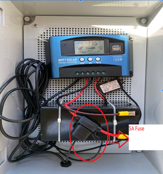
Fig 18. 5A fuse between the battery + terminal and the charge controllerCheck for the 5A fuse between the charge controller and the battery-positive terminal as shown in Fig 18. If the fuse is blown, replace it with another 5A fuse or proceed to the next step.
2. Check the solar panel for any shading or dust deposits; if any, clean it with a soft cloth (preferably cotton).
3. Check for any wiring issues(i.e. break in wiring).
4. Check the charge controller if the battery voltage is above 11V.
5. Check the sensor connectivity with the Wi Fi (by checking for the sensor over the Purple Air sensor cloud network). If not, follow the steps to reconnect as mentioned above in installation B.
6. If the sensor AQI readings are incredibly high on regular days, check for a nearby pollutant source. If no pollutant is observed, gently wipe the Purple Air sensor with a clean, dry cloth.
Even after trying the above troubleshooting steps, if the system is still not online, please contact our system support team by
Email-
Phone-
While contacting our customer support, please keep this information handy.
The standalone solar-powered air quality monitor system is a valuable device for keeping track of the outdoor air quality index, especially during wildfire and smoke conditions, and thus providing reliable information to the community so that proper mitigation and precaution could be taken to protect them from wildfire hazards. The user should follow the above instruction to ensure the system's satisfactory performance and protect the user from possible hazards. It is a good investment for homeowners and commercial users to observe the air quality and take necessary precautions or mitigation measures for protection from hazardous smoke events, which may cause respiratory illness, cardiovascular illness and other serious health issues.

.jpg)

.jpg)