
TissueDB/Simulators/Tourniquet Simulator

The Tourniquet Simulator is a low-cost trainer built from locally available wood, PVC pipe and hardware for practising tourniquet application to control life-threatening extremity haemorrhage in trauma and prehospital care.[1] Developed by CrashSavers, it pairs a wood-frame model — two PVC half-pipes as the limb surface over a spring-compressed latex-hose fluid circuit — with a mobile self-assessment app: applying a tourniquet to the surface compresses the springs onto the hose and stops the simulated blood flow, giving the learner immediate visual feedback of effective occlusion.[2] Original build instructions are at the CrashSavers Tourniquet Simulator page and the Step-by-Step Building Manual (PDF).
| Field | Details |
|---|---|
| Features and Basic Operation | Applying a tourniquet to the PVC limb surface compresses the spring-loaded latex hose and stops the simulated blood flow, giving immediate visual feedback of effective occlusion. A companion mobile app supplies a self-assessment checklist so the learner can practise without an instructor. After assembly the spring and tubing tension is calibrated — a blood-pressure cuff can set a realistic flow — so a correctly-applied tourniquet stops the flow (see the CrashSavers Calibration Manual). Train with a commercial windlass tourniquet (for example a Combat Application Tourniquet) or, where one is unavailable, an improvised sheet-and-board tourniquet. |
| Current Development Status | Content-, construct- and training-validated (Jhunjhunwala 2024); first-responder field validation underway. |
| Estimated Build Time and Cost | US$50 |
| Specialized Tools and Equipment | Hand saw; drill with 1/8 in, 5/16 in and 5/8 in bits; Phillips screwdrivers; wrenches; pliers; measuring tape; C-clamp; 400-grit sandpaper; scissors (fluid system). Optional: rotary tool (Dremel). |
| Version | Version 1 |
| Development Team Contact Information | CrashSavers (trauma surgeons, doctors and engineers; Guatemala, Chile, USA and Brazil). Corresponding author: Rashi Jhunjhunwala (rjhunjhu@bidmc.harvard.edu, per the 2024 publication), Beth Israel Deaconess Medical Center / Harvard Program in Global Surgery and Social Change. |
Tissues
| Tissue | Qty | Material | Cost | Notes |
|---|---|---|---|---|
| Skin | 2 | PVC pipe, 10 cm (4 in) diameter | $3.00 | The limb contact surface the tourniquet is applied over. |
| Blood vessel | 1 | Latex plastic hose, 5 mm (3/16 in) diameter, 1 m (39 in) length | $4.00 | Threaded through the compression zone beneath the PVC half-pipes; spring compression squeezes it shut when a tourniquet is applied. The source shopping list sells these in twos; the build uses one. |
| Blood | 1 | Water | — | Circulated through the latex hose by the hand pump; flow stops when the tourniquet is correctly applied. |
Structural Parts
- Parts Reference
-
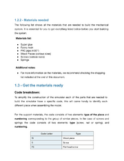
-
-


| Part Name | Qty | Material | Cost | Notes |
|---|---|---|---|---|
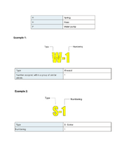
| Frame long sides (W-1) | 4 | Wood pieces | $5.55 | 300 × 20 × 10 mm (12 × 0.8 × 0.4 in). Two holes Ø5.0 mm per source diagram. |
| Frame short sides (W-2) | 4 | Wood pieces | incl. | 150 × 20 × 10 mm (6 × 0.8 × 0.4 in). Five holes Ø5.0 mm per source diagram. |
| Spring-post crosspiece (W-3) | 1 | Wood piece | incl. | 240 × 20 × 10 mm (9.5 × 0.8 × 0.4 in). Three Ø6.0 mm holes accommodate vertical S-3 posts; two Ø5.0 mm holes secure W-3 to the frame (per source diagram). |
| Horizontal base beams (W-4) | 2 | Wood pieces | incl. | 500 × 40 × 10 mm (20 × 1.6 × 0.4 in). Two holes Ø5.0 mm. Requires 40 mm wide stock (per source diagram). |
| Spring compression guides (W-5) | 4 | Wood pieces | incl. | 175 × 20 × 10 mm (6.9 × 0.8 × 0.4 in). Two holes Ø5.0 mm per source diagram. |
| Base board (W-6) | 1 | Wood board | $3.20 | 600 × 400 × 10 mm (23.5 × 15.75 × 0.4 in). Notch at top per source diagram. |
| Secondary guide/brace (W-7) | 1 | Wood piece | incl. | 240 × 20 × 10 mm (9.5 × 0.8 × 0.4 in). Two holes Ø5.0 mm per source diagram. |
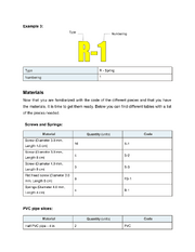
| Frame assembly screws (S-1) | 16 | Screws 3.0 mm × 4.5 cm (1/8 × 1-3/4 in) | $1.60 | Secure W-1 and W-2 frame layers at corners. |
| Frame extension screws (S-2) | 4 | Screws 3.0 mm × 8.0 cm (1/8 × 3 in) | $0.41 | Attach horizontal base beams W-4 to frame. |
| Centerline post fasteners (S-3) | 3 | Screws 4.0 mm × 8.0 cm (5/32 × 3 in) | $0.31 | Create three vertical posts arrayed along W-3 crosspiece centerline. |
| Mechanism mounting screws (FS-1) | 8 | Flat head screws 3.0 mm × 8.0 cm (1/8 × 3 in) | $0.50 | Install spring compression guide mechanism with W-5 plates. |
| Small fastener nuts | 36 | Nuts 3.0 mm (1/8 in) | $1.85 | Secure S-1, S-2, and FS-1 screws. |
| Large fastener nuts | 6 | Nuts 4.0 mm (5/32 in) | $0.31 | Secure S-3 centerline post screws. |
| Compression springs (R-1) | 4 | Spring 4.0 mm × 4.0 cm (5/32 × 1.6 in) (cut from one 30 cm (12 in) spring) | $3.97 | Cut one 30 cm spring into 4 equal pieces for the four R-1 compression positions. |
| Connection sealant | 1 | Teflon tape | $0.25 | Wrap hose connections to prevent leaks. |
| Fluid pressure pump | 1 | Water pump (fumigator) | $15.00 | Creates fluid pressure. Hand-operated, 1–2 L reservoir. |
| Water reservoir | 1 | Plastic water bottle | $1.50 | Collects water returning from circuit. Standard 1 L bottle. |
| Wood joint adhesive | As needed | Super glue | $2.68[3] | Reinforce wood joints during frame assembly. Listed by the source as a home/local-store item. |
| Structural bonding agent | As needed | Epoxy resin | $5.98[4] | Permanent structural bonds in frame. Listed by the source as a home/local-store item. |
| Hose securing ties | As needed | Plastic ties | $3.85[5] | Secure hose at 3 points along frame. Do not overtighten. Listed by the source as a home/local-store item. |
Build Instructions
Resources
- Source PDF: Simple Tourniquet Simulator — Step by Step Building Manual
- Wood cutting diagrams: Wood Diagrams (external link) or see Section 4.1.1 of the PDF above.
Tools Reference

For complete tools list, see the Step-by-Step Building Manual (PDF).
Phase 1: Preparation
Step 1: Cut all wood pieces to the dimensions specified in the Structural Parts table above. Use the wood cutting diagrams for precise measurements and hole positions. Sand all cut edges with 400-grit sandpaper.

Step 2: Drill all holes in each wood piece per the diagrams. W-1: 2 × Ø5.0 mm (3/16 in). W-2: 5 × Ø5.0 mm (3/16 in). W-3: 3 × Ø6.0 mm (1/4 in) + 2 × Ø5.0 mm (3/16 in). W-4: 2 × Ø5.0 mm (3/16 in). W-5: 2 × Ø5.0 mm (3/16 in). W-7: 2 × Ø5.0 mm (3/16 in).
Step 3: Prepare PVC half-pipes: Cut a 10 cm (4 in) PVC pipe lengthwise into two equal halves. Sand cut edges smooth.
Step 4: Cut springs: Cut the 30 cm spring into 4 equal pieces. These become the R-1 compression springs.
Phase 2: Mechanical System
Safety note: Wear appropriate safety gear (eye protection, gloves) during all cutting and drilling operations.

Step 1: Assemble the base frame rectangle using 2× W-1 (long sides) and 2× W-2 (short sides) per dimensions in the Structural Parts table above. Secure corners with S-1 screws (3.0 mm × 4.5 cm (1/8 × 1-3/4 in)) and 3.0 mm (1/8 in) nuts.


Step 2: Attach a second layer of W-1 and W-2 pieces on top of the first layer, creating a double-height rectangular frame. Secure with additional S-1 screws. This doubled frame provides rigidity.

Step 3: Insert three S-3 screws (4.0 mm × 8.0 cm (5/32 × 3 in)) vertically through W-3's three Ø6.0 mm holes to create three vertical posts in a row along the crosspiece's centerline. Secure with 4.0 mm (5/32 in) nuts on the underside.

Step 4: Verify W-3 is rigidly attached as a fixed crosspiece spanning the rectangle's interior, with three vertical posts arrayed along its length.

Step 5: Attach the two W-4 horizontal base beams (40 mm (1.6 in) wide stock) to the frame using S-2 screws (3.0 mm × 8.0 cm (1/8 × 3 in)) per dimensions in the Structural Parts table above. These run horizontally and form the main structural base for supporting the PVC half-pipes above.


Step 6: Build the frame walls — attach additional wood pieces to create the enclosure sides.


Step 7: Install W-7 as a transverse cross-brace for structural rigidity.


Step 8: Verify W-3 crosspiece assembly: confirm three S-3 vertical posts protrude upward from W-3 with 4.0 mm nuts secured underneath, ready to receive the spring stack and W-5 compression plates in Step 10.

Step 9: Place the two PVC half-pipe sections onto the frame. These form the simulated limb surface onto which the learner applies the tourniquet.


Step 10: Install the spring compression guide mechanism using FS-1 flat head screws (3.0 mm × 8.0 cm (1/8 × 3 in)) and the four W-5 guide plates. Load the four R-1 springs (4.0 mm × 4.0 cm (5/32 × 1.6 in)) between the guide plates. This mechanism provides resistance when the tourniquet compresses the PVC half-pipe down onto the springs.

Step 11: Final mechanical assembly — secure the PVC half-pipes to the frame. Verify that springs are properly tensioned and that pressing down on the PVC surface compresses the springs smoothly. The mechanical system is complete.
Phase 3: Fluid System
- Fluid System Components and Tools
-
-


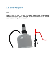
Step 1: Insert one end of the latex hose (5 mm (3/16 in) diameter) into the fumigator (pump sprayer) nozzle. Wrap the connection with Teflon tape to create a watertight seal.
TEST: Pump water through the system before continuing to verify the seal holds. Fix any leaks before proceeding.

Step 2: Thread the latex hose through the middle of the mechanical system, running it lengthwise through the compression zone beneath/between the PVC half-pipes. The hose must sit in the path where spring compression will squeeze it when a tourniquet is applied.

Step 3: Use plastic cable ties to secure the hose at 3 points along the mechanical frame. Caution: Do not overtighten — the ties should hold the hose in position without restricting fluid flow when no tourniquet is applied.

Step 4: Place the remaining hose end into the water reservoir (plastic water bottle). Wrap this connection with Teflon tape as well. Fill the bottle with water.
References
- ↑ 1.0 1.1 Jhunjhunwala R, et al. A low-cost, DIY tourniquet simulator with built-in self-assessment for prehospital providers in Guatemala city. World Journal of Surgery. 2024. doi:10.1002/wjs.12158. PMID 38526473.
- ↑ 2.0 2.1 CrashSavers Trauma/Tourniquet/Simulator. Appropedia. Available at: https://www.appropedia.org/CrashSavers_Trauma/Tourniquet/Simulator
- ↑ 3.0 3.1 Walmart, Loctite Super Glue Liquid Tube (2 tubes of 0.07 oz / ~2 mL each), product page, retail price retrieved 10 May 2026.
- ↑ 4.0 4.1 Home Depot, Gorilla 0.85 fl. oz. Epoxy (Model 42001, 5-minute set, 2-part syringe), product page, retail price retrieved 10 May 2026.
- ↑ 5.0 5.1 Walmart, Bates Cable Zip Ties 200-pack 4-inch nylon, retail price retrieved 10 May 2026.
| Alternative names | CrashSavers DIY Tourniquet Simulator CrashSavers Tourniquet Simulator |
|---|
| Authors | Arturopelayo |
|---|---|
| License | CC-BY-SA-4.0 |
| Cite as | Arturopelayo (2026). "TissueDB/Simulators/Tourniquet Simulator". Appropedia. Retrieved July 15, 2026. |