
The Supermileage Systems Enterprise (SSE) Team at Michigan Tech is a student-led team with the goal of producing and competing a hyper fuel efficient vehicle against other collegiate teams. The SSE team will compete in the 2022 Competition with a vehicle built in 2019, but there are currently several Senior Design (SD) teams on the SSE team who are designing an entirely new vehicle for the 2023 Competition.
As one SD team finishes up the design for the belly pan and the outer aerodynamic shell of the new vehicle, my solo SD team has been tasked with designing several of the internal body structures necessary to create a rule compliant and fully functional vehicle.
My Internal Body Structures (IBS) SD team has the goal of designing the safety roll bar, the internal wheel guards, and the aerodynamic shell seam for the new vehicle.
Roll Bar Design[edit | edit source]
The roll bar is the most design-intensive aspect of my SD project, and therefore has taken up more of my design time during the S2022 design season. Because this vehicle feature is directly related to the safety of the driver in the event of a roll-over during competition, there are several rules concerning its construction. Most notably, the roll bar must withstand 250 lbf in any direction from the top most part of the roll bar as per Figure 1.
In order to meet this design requirement while maintaining an optimally light design, many different materials were considered for the roll bar construction.
Material Selection[edit | edit source]
The 2022 vehicle has a roll bar made out of carbon fiber sleeves laid up around an internal 3D printed PLA core. Despite the success and the relatively light design of this roll bar, this design could still be improved. To consider more options, the following list of materials were considered for the new roll bar construction:
- Carbon fiber with an internal core
- PLA 3D printed core
- Balsa wood core
- Structural foam core
- Pre-preg carbon fiber
- Inherently hollow design w/o need for an internal core
- Machined aluminum
- Bent aluminum tubing
- Cast aluminum
- Machined magnesium alloy
- Cast magnesium alloy.
This list of possible manufacturing routes was narrowed down to carbon fiber with an internal core and either machined or bent aluminum construction. Carbon fiber is the optimal choice because it is theoretically ⅓ the weight of aluminum at the same strength. To improve upon the 2022 carbon fiber design, which exhibited a weight similar to that of a roll bar made of aluminum due to the heavy 3D printed core, a vinyl foam core was chosen as the internal core instead. This foam was chosen over balsa wood because it has a density of 3lb/ft^3 vs 9lb/ft^3 for balsa wood. While carbon fiber is the lightest option, due to past inconsistencies with carbon fiber manufacturing, an aluminum construction is still being considered. The other manufacturing techniques were ruled out due to a lack of knowledge, experience, and equipment required to complete them.
Material Testing[edit | edit source]
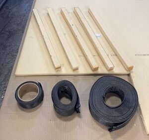
To begin to characterize the mechanical properties of the chosen carbon fiber manufacturing process, several test lay-ups were created using the vinyl foam core with varying thicknesses of carbon fiber. Figure 2 shows the vinyl foam core chosen with the varying thicknesses of carbon fiber used for the test pieces. The foam is Divinycell 3lb Density foam, and thicknesses of 3K, 6K, and 12K carbon fiber were chosen to test with. The 2022 vehicle roll bar was constructed with one layer of 6K carbon fiber, and therefore, no thicker layers of carbon fiber were tested to ensure the new design is lighter.
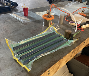
To create the test parts, a utility knife was used to cut the stiff, ½ inch foam sheet into 1 inch strips 20 inches long. Two of these strips were then stacked on top of each other to form 1in x 1in square internal cores. This geometry was chosen because the current roll bar has a 1in x 1in internal core that is proven to meet safety requirements. With the foam cut to shape, the different layers of carbon fiber shown in Table 1, were laid up around the cores using a wet-lay process. Table 1 also shows the weight foam cores, the carbon fiber, and the total amount of resin used in each test piece. The wet-lay process is shown in Figure 3.
| CF Layer | Foam Weight [g] | Pre layup weight [g] | Post layup weight [g] | Total resin used [g] |
| 3k | 16 | 16 | 45 | 13 |
| 3k+3k | 16 | 32 | 67 | 19 |
| 6k | 16 | 33 | 66 | 18 |
| 12k | 16 | 45 | 82 | 21 |
Mechanical Testing Results[edit | edit source]
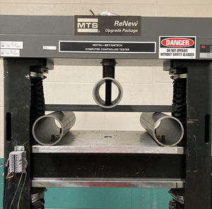
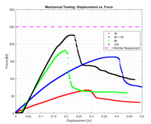
Each of the four test samples were put through the same 3-point bend test and the max applied force for each was gathered. The test setup for the 3-point bend test is shown in Figure 4. The results of the testing are shown in Figure 5. Note that the testing is in preliminary stages, and the sample size of one for each test specimen will only be used to determine a more insightful testing plan. Figure 5 shows that none of the four samples surpassed the 250lb required force. Even if the 12K sample was doubled, its factor of safety wouldn't surpass two, which is the minimum design goal of the roll bar. While initially concerning, given how the current roll bar is constructed of only one layer of 6K carbon fiber, this test does not replicate the real life testing conditions of the roll bar. One major component of the roll bar is the firewall that separates the driver from the engine within the vehicle shell. This firewall is connected directly to the roll bar, and must be made of 0.04 in aluminum sheet. As a final assembly in the vehicle, and due to a test weight that is distributed instead of pinpointed like the 3-point bend test, the lighter construction roll bar of the 2022 vehicle with the firewall attached is able to pass inspection and hold 250lbs. This testing will be re-evaluated and more factors will be considered in future testing.
Roll Bar Future Plans[edit | edit source]
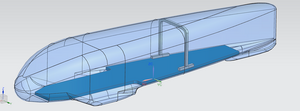
This SD project is only half way complete, and a lot more needs to be accomplished before a final roll bar design is implemented into the new shell. More test samples will be created, including aluminum test samples, and tested in different ways to try and figure out the most accurate way to test their strength before one design is chosen for the final constructions. A computer aided design (CAD) model of the roll bar within the new vehicle shell is shown in Figure 6. This design was created to match the geometry of the shell and the belly pan of the new design, and in the future it will be used for finite element analyses (FEA) to further validate material design. Different layers of carbon fiber laminates will be analyzed in addition to aluminum bar construction.
Wheel guards[edit | edit source]
Because the 2023 vehicle includes fully enclosed wheels, there must be wheel guards that prevent the driver from propelling the car. While the wheel guards are also a safety feature, they are mainly to prevent teams from cheating. While the design for the wheel guards is in its very early stages, it is planned that a wire mesh will be used to create them. The current vehicle has carbon fiber wheel guards. While these carbon fiber guards are very light, they are flimsy and difficult to mount within the vehicle. In order to maintain a lightweight design but increase ease of adaptability to make quick changes easier, a wire mesh design will be used. The wire mesh will be easier to work with and shape on the spot, and L-bracket type snap points will be 3D printed and attached to the vehicle shell to ensure the wheel guards can be easily attached and removed for maintenance purposes.
Seam Design[edit | edit source]
Seam design is also in the very early stages of development, but it has been decided to create overlapping portions of the shell that incorporate magnets and ferrous metal on each side to make attachment and alignment very easy while maintaining the aerodynamics of the shell.