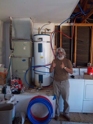
Description of Project[edit | edit source]

Build a solar batch water heater and install at my residents in La Quinta, California. My initial proposal was of my own design and this has not changed but I did make some changes as the project progressed currently have no regrets with my final project other than some changes which still need to be made but I was expecting changes and some cost over runs.
Changes to Original Design[edit | edit source]
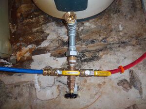
The first major change came when I decide to make a ¾ inch copper grid instead of using an old hot water tank. I do think the water tank will work and I may install an additional tank in future. The second major change was I found a T valve which was designed to be used on a conventional water heater by removing the drain spigot this prevented additional plumbing. The T valve works as advertised. The other change which I was not aware of until I got ready to install and I went for my permit was that I could use PEX but only in the interior household piping.
Building the Solar Water Heater[edit | edit source]
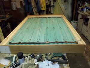
The box design from the bottom to the top was as follows 1 4' x 6' piece of ½ inch plywood, 2 6' pieces of 2 x 2" pieces and 2 4' pieces of 2" x 2" for framing on top of ½ plywood piece on the bottom, next came another piece of 4' x 6' ½ plywood to put on top of 2" x 2" frame, between the two pieces of plywood was placed some insulation which was recycled from a job my father had done. A quick note the plywood was also recycled from an old job. Next I took some aluminum roofing material (recycled) which I had to flatten with a sledge hammer which I attached to the top of the plywood with roofing nails. Next the copper grid was laid in place. I will go into more detail on the grid design after I finish discussing the box design. I took two copper pipe clamps to secure to box frame and then placed pre bent recycled aluminum roofing over the copper grids. I secured this with four copper clamps on each section of pipe to hold down and make a good tight contact with the copper pipe and the aluminum under frame. I then took two more 6' and 4' 2" x 2" pieces and made a frame on top of the aluminum along the edge of the plywood frame so the glass would have place to sit and I would be able to support the 1" x 6" frame which would go around the the box being sure to line the 1" x 6" with the bottom of the box leaving the addition inches sticking up so to keep the glass in place. Next I spray painted the interior of the box with flat black paint designed for use on barbeques meaning it could handle temperatures of up to 1200 degrees. I then put a clear waterproof silicone around the interior of the frame and placed the glass (1/4 inch tempered)on the silicone to create a waterproof seal. The silicone has a working temperature range of – 60 degrees to 400 degrees. That completed the box. Another note the reason I designed it to be 4' x 6' is because that is what would fit in the bed of my truck. See next section on how to build copper grid from scratch. If you would rather not you could have someone build the copper grid for you and then build the box yourself. I am a big fan of options.
Building the Copper Grid[edit | edit source]
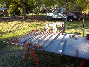
The copper pipe grid was specifically designed to fit on 4' x 6' plywood frame. I cut 8 - 4 foot ¾ inch copper pipe sections and 14 - 4 inch copper sections. I did this using a copper pipe cutter. Note after cutting copper be sure to remove the copper lip which forms when cutting copper so as to not restrict water flow. Then I took 14 ¾ inch copper T joints and 2 90 degree copper elbow joints. Then I cleaned all the joints, fluxed all joints while assembling the grid. Then using lead free solder and a torch and sealed the joints with solder. I then tested it for leaks by sealing one end and filling it with water for 4 to 5 hours. Be sure to clean and flux joints to ensure proper seal from solder.
Installing The Water Heater[edit | edit source]
To install water heater on roof I took 2 - 74 inch pieces of 2" x 6" and with 3/8 inch drill bit drilled four holes and secured them to the roof with 4 inch lag screws. Before installing lag screws I dipped them in roofing tar to ensure waterproof seal when securing 2" x 6" pieces to the roof. Then I installed corner brackets.
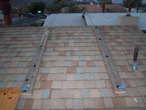
Installed the solar water heater on my roof which was no easy task I would estimate the box with wood, copper and glass at around 200 pounds.
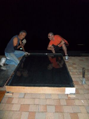
Then I drilled to holes in the roof with 1 and ¼ inch drill bit and made a cut in the shingle to place roof flashing with tapered 1 inch shaft. Next came the plumbing I used copper on the exterior and PEX pipe on the interior. The series of pictures below will help to understand the process. I can go into more detail if needed later.
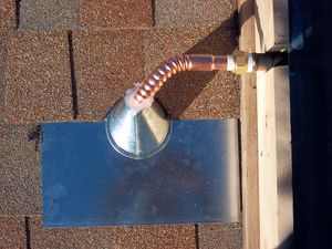
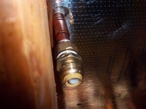
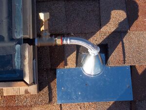
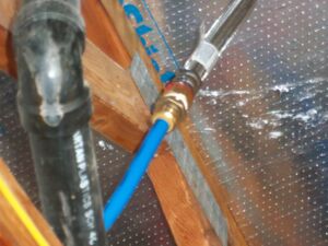
T valve connected to water heater in place of drain spigot. This is the T valve I mentioned at the beginning. Shark bite couplers on the hot and cold ends. Note: Pump will be installed on cold side of T valve once it is reordered since I broke the first one. Also, the brass fitting nearest the water heater is a brass thermal well for temperature sensors coming from differential controller. This will make the solar water heater active rather than passive

Cost of Project[edit | edit source]
Wood – $16.00
Fitting and pipe – $300.00
Glass – $215.00
Differential controller, pump, T valve and thermo wells – $240.00
Total cost so far: $771.00
Final Thoughts[edit | edit source]
My electric bill should go down about 30 dollars per month so my breakeven point is 2 years 3 months. With only some minor changes I think my solar water heater will provide many decades of service next project design a solar photovoltaic system. Wish me luck.
Contact details[edit | edit source]
jgranado2000@yahoo.com.