Lesson 2[edit | edit source]
SketchUp: a home from A to Z[edit | edit source]
Introduction (setting units)[edit | edit source]
Choose Window -> Preferences. The Settings-menu appears. At the option "Template" (or "units"), you can specify what units you want to draw. We choose millimeters for architectural models.
(Introduction) Importing an AutoCAD-drawing (.dwg or .dxf-file)[edit | edit source]
Choose File -> Import in the menu.
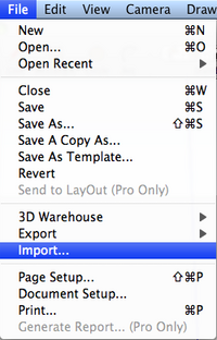
Following window opens:
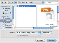
Set the "format" to "ACAD Files" (*.dwg, *.dxf) and select the image you want to import.
Remember to indicate with which units you drew your AutoCAD-drawing using the "Options"-button (the example drawing was drawn in millimeters). That way you do not need to tamper on the scale later-on.
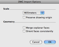
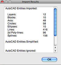
Once you click on the "Import"-button (click OK first offcourse in case you changed the options), a progress bar is displayed, and once the importing has been completed, a type of report is displayed (just click OK).
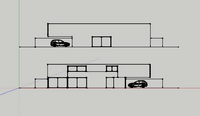
The AutoCAD drawing has now been imported.
Some comments:
- If you do not see the imported drawing, you might be zoomed in too closely or zoomed out too far. Click on "ZOOM extents" (or shift + z) to get everything displayed correctly within the screen.
- An imported drawing is standardly layed out on the ground plane (XY plane).
- SketchUp recognizes all AutoCAD-geometry; you can select lines, SketchUp's inference recognizes endpoints, midpoints, ... An ideal cooperation.
(Introduction) Basing a SketchUp-model on an AutoCAD-drawing[edit | edit source]
Now that you imported the picture, and now that you know that SketchUp handles the imported drawing so smoothly, you can begin to redraw the AutoCAD-lines (with the LINE-tool), so that surfaces are created which you can then turn into volumes (with the PUSH/PULL-tool).

NOTE: Select the entire AutoCAD-drawing before commencing on this, and make it a group. If you do not do this, you will encounter a multitude of unpleasant surprises ! (as too is common, if you do not use enough groups)
The house[edit | edit source]
After this AutoCAD-introduction, we now have an example where we start off from a JPEG-image as an underlayer. We will work further with this example. The cooperation between an image and SketchUp is less intelligent than between AutoCAD and SketchUp, so we will have more work to do, and we will learn somwhat more off of it.
Setting units[edit | edit source]
Choose Window -> Preferences. The Settings-menu appears. Under the option "Template", you can specify in what units you want to draw in. We choose millimeters for architectural models.
Importing a JPEG-underlayer[edit | edit source]
Via File -> Import, we can import the underlayer. Different file types are eligible for importing:
- CAD-drawings
- Images (JPEG, TIF, ...)
It is important that you indicate what file type you want to import at the bottom.

If you, for example, selected AutoCAD-files as type, only AutoCAD-files will appear in the selection window ! Choose as underlayer the following (JPEG-)image: onderlegger.JPEG
When you click "Open", the chosen image will hang off your mouse pointer. The first click determines the position of the image, a second click determines the size.
Scaling the underlayer[edit | edit source]
You just indicated the size of the underlayer by clicking for a second time. This can however not be determined on sight and must thus be considered incorrect. We will thus have to scale the underlayer to the right scale. We do this as follows:
- We start off from a known size, for example a doorway which is usually 900 mm wide.
- We then remeasure its size. This is done using the TAPE MEASURE-tool (shortcut T or Menu -> Tools -> TAPE MEASURE). Click on the starting point, and then on the end point of the known size. At the bottom right corner, the length of the line is shown.
- Now, by directly typing in the length that the line should have, the line is rescaled (and thus the entire model as well). We type in 900. SketchUp then asks whether the entire model can be scaled. This was our intention, so we answer yes.
Drawing the walls[edit | edit source]
Now the underlayer is imported and scaled, we can base ourselves upon it to draw the walls of the house. Use herefore the LINE-tool, and also take SketchUp's inference into account.
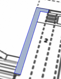
Giving a height to the walls[edit | edit source]
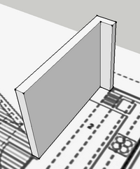
Use PUSH/PULL to give the correct height to the walls. In our case; 2500mm.
- Select PUSH/PULL
- Select the surface that you want to give a height
- Move the mouse in the right direction (stretch surface towards the sky)
- Type in the right height (2500mm) and press the Enter-key
Repeat: drawing walls and stretching them[edit | edit source]
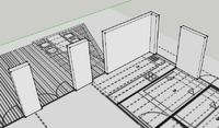
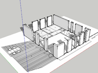
Tip: you do not need to keep typing in the height of the walls; SketchUp remembers the last entered height. Thus, when you use PUSH/PULL, and then double-click with this tool on a surface, SketchUp will use the lastly entered height ! This way we can quickly draw all our outside walls.
Drawing parapets[edit | edit source]
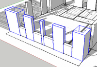
Not all openings running from floor to ceiling. Therefore, we will need to draw parapets on some places (height: 1000mm). We do this the same way:
- We draw the ground surface with the LINE-tool or the RECTANGLE-tool (The RECTANGLE-tool works faster in this particular case).
- We stretch the surface (to 1000mm) using the PUSH/PULL-tool.
Drawing lintels[edit | edit source]
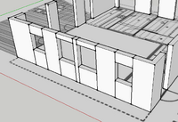
The windows-ceiling space also doesn't run through all the way. We thus draw lintels at several places: 500 or 1000mm high.
Merging wall sections (removing excess lines)[edit | edit source]
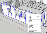
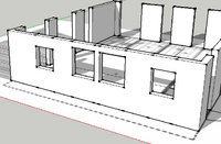
Between the wall sections, there are currently still some redundant lines. We can simply select the surplus lines and delete them (hold the Shift-key to select multiple lines). Afterwards, we select each wall and we make them a group.
Drawing the interior walls[edit | edit source]
Same method of operation.
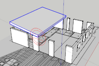
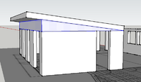
Drawing the butterfly roof (left half)[edit | edit source]
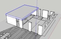
We do this in 8 steps (per roof half):
- RECTANGLE: we draw a rectangle above the left half of the building.
- PUSH/PULL: this rectangle is given a height of 300mm with the PUSH/PULL-tool.
- GROUP: this volume is made into a group
- ROTATE: this group is turned over an angle of 7 degrees.
- PUSH/PULL: a crossing of 900mm is made
- LINE: the triangle under the left roof half is drawn in profile
- PUSH/PULL: this triangle is stretched over the entire width of the house using PUSH/PULL.
- GROUP: this volume is made into a group
Drawing the butterfly roof (right half)[edit | edit source]
Repeat the above steps to also draw the right half of the roof.

Drawing a window and a door[edit | edit source]
Template:Multiple image
Template:Multiple image
Decorating the home[edit | edit source]
With Window -> Components, we open a window where we find different components for our home(furniture, objects, ...). These can be placed in the drawing to decorate the house. At http://sketchup.google.com/3dwarehouse/, we can find almost any model we want.
Exploring the model interactively (interactive camera tools)[edit | edit source]
We already learned how to work with ORBIT, ZOOM and PAN. These are the basic camera tools. You can activate all three tools with the middle mouse button, and we use them constantly while drawing. Besides these 3 basic tools, there are also 4 interactive tools: keyboard
- POSITION CAMERA
- WALK
- LOOK AROUND
- SECTION PLANE
POSITION CAMERA[edit | edit source]
With this tool, you indicate the point where you want to place the camera. (eye altitude = +/- 1.7 meters). The tool allows you to look at the model from the perspective of a person, and it thus makes the model look more realistic.
WALK[edit | edit source]
After you indicated your view point using the POSITION CAMERA-tool, you can begin to walk around. For this, you select the WALK-tool, and you use the keyboard-arrows. (You can also use the mouse to navigate, but this is less convenient)
LOOK AROUND[edit | edit source]
By selecting this tool, holding the left mouse button and moving the mouse, you can look around.
SECTION PLANE[edit | edit source]
You can use this tool to "cut" through your model, to make cross-cut plans, ... You find this tool at the bottom of the "Large Tool Set", or via the Menu: Tools -> SECTION PLANE. Once this tool has been activated, a green blade hangs off the mouse pointer. You can place this blade on each surface (in any direction) by simply clicking on the desired surface.
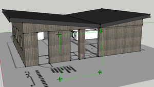
Once you have done this, the blade is placed on the surface of the model, and you see a cross-cut. The blade becomes orange.
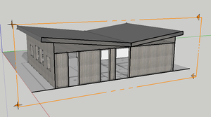
You can then easily select and move the blade with the MOVE-tool.
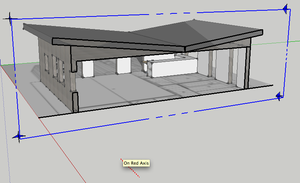
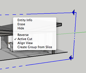
Some options: Right-clicking on the blade opens up a window menu with several options:
- HIDE: hides the blade. The blade will remain active, but will no longer cut (edge + 4 arrows become invisible).
- REVERSE: reverses the "viewpoint" of the blade.
- ACTIVE CUT: activates or deactivates the cutting. The blade remains active. Double-clicking on the blade has the same effect: activates/deactivates the cutting.
- ALIGN VIEW: positions the camera so that it looks perpendicular towards the cross-cut. (if you alsoset the camera to "parallel projection" instead of the "perspective" projection, you also attain traditional cross-cuts. With the professional version, it is even possible to export these cuts to AutoCAD for example)
- CREATE GROUP FROM SLICE: generates a 2D-cut (group).
Standard views[edit | edit source]
Within SketchUp, there are a number of standard views. You activate them with the "Views Toolbar", via the camera menu or via shortcuts (SHIFT + a digit). From left to right, we have the following views:
- Isometric
- Top
- Front
- Right
- Back
- Left

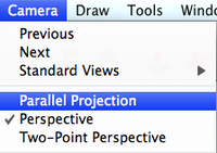
Tip: If you turn off the perspective by choosing "parallel projection" instead of "perspective" in the camera menu, you can use these default views to make plans, pictures, cross-cuts, ...
Measuring equals knowing[edit | edit source]
We can enter exact dimensions for any line, surface, ... we draw and for any other operation we perform. What to do however if we want to measure the size after we have drawn something ?
Lengths[edit | edit source]

a. The TAPE MEASURE-tool (T) and the LINE-tool (L) When you take a length measurement with anyone of these two tools (by clicking on the starting point, and then click on the ending point), the length will appear in the bottom right corner (in the VCB or Value Control Box) When you use the TAPE MEASURE-tool, the same length will also appears alongside the mouse pointer. This way of measuring does not change the drawing.

b. DIMENSION-tool If you use the DIMENSION-tool, measurement lines are placed in the drawing (the drawing hereby changes !). You place measurement lines by
- clicking on their starting point
- clicking on their endpoint
- indicating the distance between the measured element and the measuring line (= third click)
Surfaces[edit | edit source]
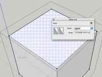
By selecting a surface, right-clicking on it, and clicking "Entity info" in the context-menu that appears, you can check the surface area of the selected surface.
Volumes, contents, ...[edit | edit source]
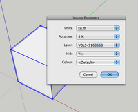
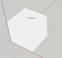
This can not be measured standardly by SketchUp. With the installation of a plug-in however, it does become possible. The plug-in is called "VolumeCalculator.rb"
