OSAT Cam Cleat.jpg
FA info icon.svg Angle down icon.svg Device data
Manufacturing files https://www.thingiverse.com/thing:1183173
Hardware license CERN-OHL-S
Certifications Start OSHWA certification
FA info icon.svg Angle down icon.svg Project data
Authors Thomas Korejsza
Made Yes
Replicated No
Cost USD 2.55
OKH Manifest Download

Cam Cleat[edit | edit source]

Project developed by Thomas Korejsza (talk) 16:55, 7 December 2015 (PST)

Abstract[edit | edit source]

  1. This OSAT design is an economical alternative for a cam cleat. Basic cam cleat designs are utilized for many functions. They are typically used as a quick release and locking mechanism for ropes and chords. These devices are usually found on sailing vessels as a method organize and hold lines. Additionally, with few modifications of this design, one being a pulley, a mechanical ascender should be able to be printed.
  2. Cam cleats typically use leaf springs to provide their action, however, this is a prototype using rubber bands. The loads for this prototype need not be large to confirm how the rest of the design responds to an action.
  3. Having the option to 3D print a cam cleat at sea is attractive as it can save frustration in the event of a failure. During light to medium wind conditions, a 3D printed cam cleat should be sufficient until a replacement can be obtained.
  4. Picture of completed print using
    OSAT Cam Cleat.jpg

Bill of Materials[edit | edit source]

  1. Materials needed for fabrication of device and alternative materials if they are not available, prices/sources of non-printable parts
  2. Plastic - roughly 66 grams of PLA which equates to $1.52 at $22.98 pr 1Kg.
  3. Rubber bands- large assortated package at $1.68
*ONLY NEED TWO BANDS!
  1. Two 3mm bolts & Two 3mm Nuts ~ $0.98
    1. Link to Thingiverse with scad and stl files.
[|https://www.thingiverse.com/thing:1183173]]

Tools needed[edit | edit source]

  1. MOST Delta RepRap or similar RepRap 3-D printer
  2. C-clamps for setting nut into base plate.

Thomas Korejsza (talk) 16:55, 7 December 2015 (PST)

Skills and knowledge needed[edit | edit source]

  • Novice skill with OpenScad is required for the modeling.
  • Knowledge of a cam cleat was required.

Technical Specifications and Assembly Instructions[edit | edit source]

  1. Directions for assembly
    1. Download the .stl and/or .scad files.
    2. Print both base plate and cleats.
    3. Insert nuts into bottom of the base plate. C-clamps help secure them to their location.
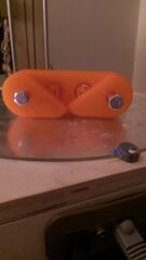
    4. Located on the base plate and cleat are pegs, use a rubber band between these two pegs to provide the spring action. (Note. you may want to double over the rubber band to create more tension.
    5. Place bolt through cleat clamp and screw into nut.
  2. print time estimate- 3 hours
  3. Assembly time estimate 5-10 minutes
  4. Including drawings or pictures of the device at stage of assembly at minimum. (Upload)

Common Problems and Solutions[edit | edit source]

  • A common issue with this design is that the rubber bands providing the action may slip off when relaxed. This can be solved two ways, either provide a lip for them to stay on or use an exceptionally tight rubber band.
  • Also, an improvement to this design would be a better stopping mechanism so the cam does not reverse on it self when relaxed.
  • Both issues can potentially be solved when using a leaf spring instead of rubber bands.

Cost savings[edit | edit source]

  1. Total cost using sum from BOM - $2.55
  2. Commercial equivalent [Harken Cam Cleat] $31.50
  3. $ savings = $28.55
  4. % savings = %90
FA info icon.svg Angle down icon.svg Page data
SDG SDG09 Industry innovation and infrastructure
Authors Thomas Korejsza
License CC-BY-SA-3.0
Organizations MTU, Michigan_Tech's_Open_Sustainability_Technology_Lab
Language English (en)
Related 0 subpages, 2 pages link here
Impact 444 page views
Created December 8, 2015 by Thomas Korejsza
Modified February 28, 2024 by Felipe Schenone
Cookies help us deliver our services. By using our services, you agree to our use of cookies.