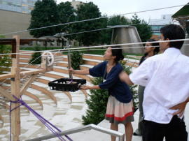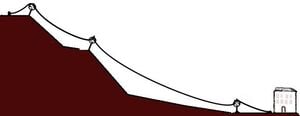

This Project stems from the need of an Indian community in the state of Uttarakhand. A women's cooperative in the village of Ranikhet produces roof tiles and various preserves. However, to bring them to the market they must carry heavy loads up steep hills daily. This project attempts to design an affordable ropeway to do that same task in a less strenuous manner.
Introduction[edit | edit source]
- Pan Himalayan Grassroot Development Foundation
- More details about Umang and the work there
- Use of ropeways in India and Nepal.
- The specific case of Umang.
Materials and Cost[edit | edit source]
In the case of this particular ropeway, most materials can be obtained locally (in the closest industrial city). The exact cost depends on the choices of materials and how much is assembled at the ropeway (for example if the towers are just built with local materials by the locals or transported from 100miles away).
Industrial supplies such as tubing (for the towers) and steel cable can be obtained at Chandigarh 280 km (175miles) away. Some of the materials can be obtained from recycled ones, but one has to do specific on-site safety analysis for their use.
Among some of the possibilities for recycling we found:
- Using car springs to compensate for the temperature variation in sag.
- Using car wheel rims to work as pulleys
Both these alternatives require further investigation and are adapted to low weight applications (Human transport needs to be excluded until experiments are done to test their strength).
Technical Calculations[edit | edit source]

To design the ropeway and ensure its safety we must address the following questions:
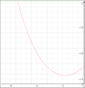
- What will be the sag "h" of the rope between towers?
- For a given sag "h", what will be the tension "T" of the rope?
- How will the temperature alter the sag of the rope?
- How many intermediate stages or towers are necessary to hold the rope?
A first approximation can be made using some online resources. For instance,
- | Sag and Tension in Antenas provides interesting details and numbers.
However we must also adapt the calculations to the particular case at hand. The specific materials, temperatures and the topography can alter significantly these parameters.
A second interesting reference comes from river crossing ropeways (also known as wire bridges or Tuin).
Project Requirements[edit | edit source]
Describe team goals here.
DESIGN[edit | edit source]
The current ropeway is a Bi-cable and to and fro non circulating system in which two carriers of same weight on two tracks moves up and down. When one carrier goes up the other carrier at the same time moves downwards and carriers are spaced such that they will reach to the two boarding stations at the same time so that loading and unloading can be done simultaneously reducing the time. Rope: For our ropeway we chose ………………………..rope. It has the following characteristics
1. Track rope[edit | edit source]
Strength
Diameter
Weight density
Material Thermal expansion co-efficient
No of strands
Type
No of strands Direction of lay No of wire in each strands Type of core Arrangement of wires in strand
2. Hauling rope[edit | edit source]
Strength
Diameter
Weight density
Material Thermal expansion co-efficient
No of strands
Type
No of strands Direction of lay No of wire in each strands Type of core Arrangement of wires in strand
Ropeway carrier[edit | edit source]
In our design we have two carriers almost of same design except the top wheel arrangement system. As we are working on two designs to help the cart to move over the intermediate towers so we have two different types of pulleys attached to the carrier at the top.
- One with wider space between the two flat surface which will be used if we are going to use the pipe system
- Second with the narrow gap between the two flat surfaces which will be useful if we go with the design of three flat plates.
These pulleys will roll over the track rope which will support the carrier and holds almost total weight of the carriers. A container box is attached to the hanger which in general is curved so that the container can pass the intermediate tower without hitting it. In our design we have a small piece of metal which is curved (fig ) at the end so that it can easily run over the lover stage of middle tower this curved portion is also used for moving the container with the help of the hauling rope which connected to it. It provides more balanced motion during the operation and protect container from toppling. We used a plastic container in our initial prototype.
Towers[edit | edit source]
These are supporting structures. Towers are provided with wheels or rollers. In our prototype we made two end towers of steel and an intermediate tower with wood as it was subjected to less stresses. At the each end towers there are two sheaves and two rollers and at the intermediate one there are only two wheels at the lower bar. These rollers support the hauling rope. These rollers generally have such radius so that there are less bending stresses on the rope. Towers can be made of wood, concrete, steel and other material according to the need (load and distance).
Sheaves[edit | edit source]
These are wheels with large radius. The hauling rope passes through the sheaves. The driving sheaves are those which get power from some source to move the hauling rope. Generally the other end sheave are not power operated they simply respond the powered one and only rotates due to tension on the hauling rope.
Stations[edit | edit source]
There are mainly three kind of stations in a ropeway system
- Drive station:
- where the source of power is situated to drive the ropeway. Generally has some sort of system to provide a constant tension in the ropes because due to temperature change the length of the ropes changes. In our further design we are hoping to use cars leaf springs to provide a constant tension in ropes.
- Intermediate stations:
- these are located at appropriate locations to provide the ropeway support and to limit the sag in rope so that it can not touch the earth or any structure.
- Return stations:
- from this station the container moves back to the driving station. It has the return sheaves.
Our ropeway design[edit | edit source]
In our ropeway we used a looped non circulating bi- cable ropeway system. In this type of system the containers move back and forth to the stations. For doing this we have to change the direction of motion every time container reaches their destinations. It is easy to do if you have a three phase electric supply as it was available in our case. The track cable is fixed and hauling rope is used for moving the carts which are equiv.-distant from each other. The containers don't circulate around the sheaves. They remain on the same side on the ropes.
[The Intermediate Problem]
In our project the major problem was to move the container over the intermediate tower. Because if don't have a good mechanism to do this the cart would hit the tower and it would be impossible to pass through the tower.
Solution[edit | edit source]
We came with the two possible solutions
1. The Pipe System[edit | edit source]
in this system the track cable goes inside a small piece of pipe (fig) and this piece is welded to the top bar of the intermediate structure. When ever a container will come the pulleys attached on the top of the hanger will simply go over this pipe piece and after passing this it will again come back on the rope. The size of the pipe depends on the diameter of the rope. The ends of the pipe were made in such a shape so that the pulleys can easily shift from the rope to pipe and from pipe to the rope. Also the space between the two ends of pulleys should be greater than the diameter of pipe.
2. Three Flat Plate System[edit | edit source]
in this system the we had used three flat plates arranged (fig. ) in such a way that they have a gap equal to the diameter of the rope and a very little clearance (few millimeters). For this the sandwiched plate should have a thickness equal to distance as stated. Whenever the cart will come it will make a shift from the rope to the plates and again to the rope. To make the shift easier the length and height of the plates should be appropriate so that there is a low angle of inclination. These three plates are welded together and again welded to the bar at the top of the intermediate tower.
More about the design coming soon...

Contact details[edit | edit source]
- ab1805 [-@-] ic.ac.uk
- Sunil Singh Jethuri
- Dehradun Institute Of Technology, India
- suniljets@gmail.com
Intro[edit | edit source]
- Ropways in Nepal, context, constraints, and co-evolution
- Gyawali, Dipak., Dixit, Ajaya., Upadhya, Madhukar.
- Published in 2004,
- Nepal Water Conservation Foundation with Kathmandu Electric Vehicle Alliance (Lalitpur)
- [the book hard to find so the easiest way to buy it is to contact the editors]
Aerial Ropeways and River Crossing[edit | edit source]
- Practical Action 1,wiki
- For more detailed calculations and specifications: USGS report, Stream-Gaging Cableways
Mathematical background[edit | edit source]
- "Cable Structures"
- H. Max Irvine
- MIT Press Series in Structural Mechanics, 1981 [ISBN 0-262-09023-6 AACR2]