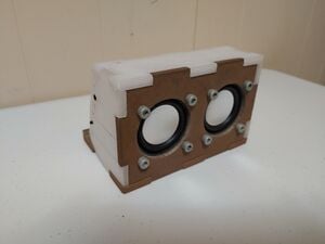
The goal of this project is to create an open source portable speaker utilizing Near Field Audio as its primary input source.
Background and Problem Statement[edit | edit source]
Most portable speakers operate wirelessly via the Bluetooth communication protocol. Near Field Audio is an alternative technology that sacrifices range for power efficiency and cost effectiveness. It also allows for devices not compliant with Bluetooth to be used assuming they have a speaker output of their own. The goal of this project is to create a portable speaker utilizing Near Field Audio as its primary input source. The box is designed in FreeCAD and completely 3D printed making modification simple.
Goals[edit | edit source]
To realize this Near Field Audio Speaker, the following goals should be met
- The project must be simple and have a low barrier to replication
- Any parts used must be 3D printed or readily accessible
- The cost to build the speaker must be $100 or less
- The project must be open source
Construction Choices[edit | edit source]
Electronics[edit | edit source]
To receive audio wirelessly a receiver is needed. With Near Field Audio (NFA) this is done via an electromagnet. In the case of this project, a 5mm in diameter 8mm length piece of soft iron was wrapped in ~4000 turns of 42 AWG enameled copper wire. While this was constructed in house, similar electromagnets can be found online for purchase. For it to receive a signal simply output an electromagnetic signal from another device in close proximity (5cm in this case). For the purposes of this project the electromagnetic signal is output from a phone speaker.
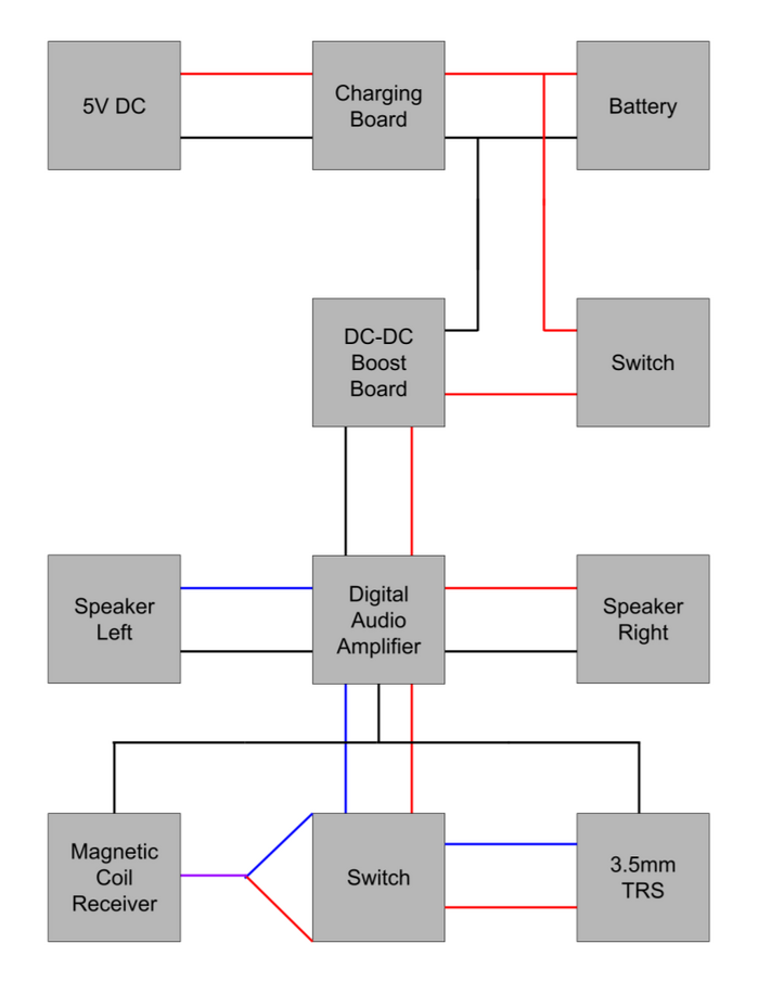
The power of the signal the received is too low for direct audio reproduction, meaning amplification is needed. Any digital audio amplifier should work. For this project a PAM8403 was used as it is low power, efficient, and inexpensive. Any other digital audio amplifier should accomplish the same thing, but would have different power requirements thus requiring different parts for power delivery. Attaching the receiver to the input of the PAM8403 allows for greatly amplified audio playback.
The power requirements of the PAM8403 are quite small, only requiring a stable 5V input. This was achieved via 3.7V Lipo battery and DC-DC voltage booster. Charging the battery is done via a Lipo charging board matching the requirements of the battery. For this project a MT3608 was used to charge the battery while a TP4056 was used to boost the voltage back to 5V. Both parts were chosen for their availability and low cost.
Of course to actually produce any sound speaker drivers are needed. In our case with the PAM8403 we are limited to two 3W 4 Ohm speaker drivers if we want to access their full power. With the parts chosen here, the playback is substantially amplified with good audio quality.
It also is a good idea to include an on/off switch, capacitor in parallel with PAM8403 power input, and some polyfil.
Box[edit | edit source]
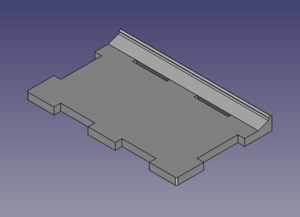
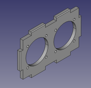
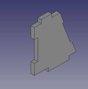
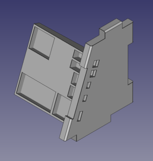
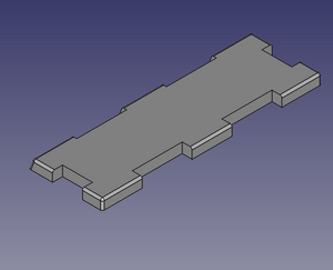
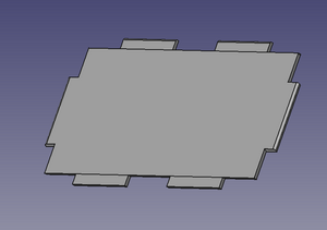
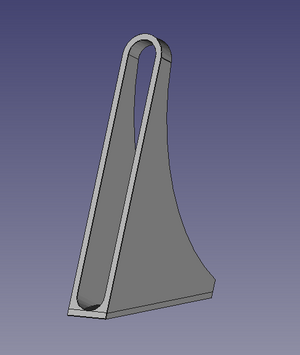
The speaker box is made of both 100% infill PETG and bronze infused PLA. This design choice is intended to reduce unintentional resonance. Each side on the speaker is its own printable model to allow for easy printing and construction. All panels are 0.25 inches thick except for the back, that being 0.1 inches thick.
Box Parts[edit | edit source]
 |
 |
 |
 |
 |
 |
 |
Validation[edit | edit source]
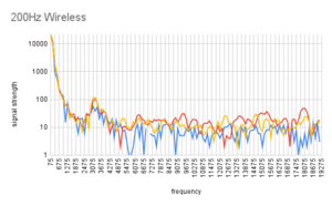
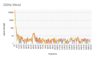
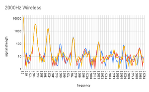
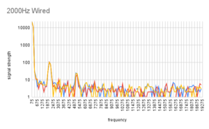
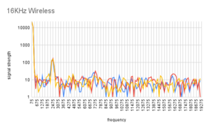
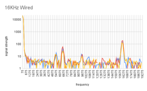
The speaker has been tested by comparing its wireless and wired input frequency response. This was primarily done through an Arduino NANO and the Arduino FHT library as well as an FFT capable oscilloscope. The speaker is proven to be accurate between 200Hz and 16KHz for wireless input and between 200Hz and 18KHz wired at minimum.
 |
 |
|---|---|
 |
 |
 |
 |
Validation Code[edit | edit source]
/*
fht_adc_serial.pde
guest openmusiclabs.com 7.7.14
example sketch for testing the fht library.
it takes in data on ADC0 (Analog0) and processes them
with the fht. the data is sent out over the serial
port at 115.2kb.

* /
# define LIN_OUT 1 // use the lin output function
# define FHT_N 256 // set to 256 point fht
# include <FHT.h> // include the library

void setup() {
	Serial.begin(115200); // use the serial port
	TIMSK0 = 0; // turn off timer0 for lower jitter
	ADCSRA = 0xe5; // set the adc to free running mode, clock divided by 32 for a sample rate of ~33.5KHz
	ADMUX = 0x40; // use adc0
	DIDR0 = 0x01; // turn off the digital input for adc0
}

void loop() {
	while(1) { // reduces jitter
		cli();	// UDRE interrupt slows this way down on arduino1.0

		for (int i = 0 ; i < FHT_N ; i++) { // save 256 samples
			while(!(ADCSRA & 0x10)); // wait for adc to be ready
			ADCSRA = 0xf5; // restart adc
			byte m = ADCL; // fetch adc data
			byte j = ADCH;
			int k = (j << 8) | m; // form into an int
			k -= 0x0200; // form into a signed int
			k <<= 6; // form into a 16b signed int
			fht_input[i] = k; // put real data into bins
		}
		fht_window(); // window the data for better frequency response
		fht_reorder(); // reorder the data before doing the fht
		fht_run(); // process the data in the fht
		fht_mag_lin(); // take the output of the fht
		sei();
		//Serial.println("start");
		for (byte i = 0 ; i < FHT_N/2 ; i++) {
			Serial.print(fht_lin_out[i]); // send out the data
			Serial.print(" ");
		}
		Serial.println();
	}
}
Future Development[edit | edit source]
Project development has concluded, but there remains possible improvements.
- Reduce receiver strength slightly to reduce noise
- Implement faraday cage doubling as speaker driver grill
- Add 3.5mm output
- Reduce box panel depth to 0.1 inches and print solely in metal infused filament
- Combine receiver stand and left side panel
- redimension box to make better use of volume
Bill Of Materials[edit | edit source]
To build a Near Field Audio Speaker of the same spec, the following parts are necessary:
| Name | Cost |
|---|---|
| PAM8403 | $4 |
| Pair of 3 W 4 Ohm Speaker Drivers | $10 |
| TP4056 | $6 |
| MT3608 | $5 |
| 3.7 V 2200 mAh Li-Po battery | $13 |
| Equivalent Electromagnet | $5 |
| Total | ~ $43 |
The price calculated here is a high estimate. All of these parts are cheaply available with the caveat of a longer shipping time.
Circuit Layout[edit | edit source]
To assemble, the following basic schematic can be followed.
Acknowledgements[edit | edit source]
The Near Field Audio Speaker team would like to thank Dr. Shane Oberloier for greatly aiding in many design choices as well as sourcing tools and resolving many project roadblocks. The team would also like to thank the OSHE LiDAR team for leaving there miniUSB cable in the lab when we forgot ours. The team would also like to thank Nicholas Whisman for allowing us to use one of his Arduino NANOs. The team would also like to thank Katty and Jon Neill for inspiring this project.