Concept Design/Selection
System Processes[edit | edit source]
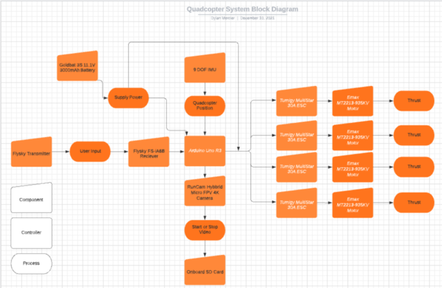
To determine the optimal parameters for the quadcopter, the system must be analyzed as a whole to determine the processes it will experience. Figure 1 below shows a block diagram of the quadcopter system, showing how each input and component is linked to one another. This diagram also shows how the process is calculated from the user inputs, to produce thrust as an output for the system. The user starts by giving input using the transmitter, which is linked to the receiver in the quadcopter. This receiver translates the input the user gave and sends the input to the Arduino. Combined with the user input, the IMU calculates the quadcopter's position in space to determine if automated inputs are necessary to keep the system stable, while the battery supplies power to various components. After the inputs are calculated by the Arduino and MultiWii software, it sends an output to the four motors and ESCs to produce the correct amount of thrust. This thrust can vary for each motor, as one motor may produce more thrust than the other three to tilt or turn the quadcopter in a certain direction. The user can also specify whether a video is to be recorded or not, where this command is sent to the Arduino, redirecting it to the camera's module, starting or stopping a video and saving it to the onboard SD card.

Determining the optimal frame size and shape[edit | edit source]
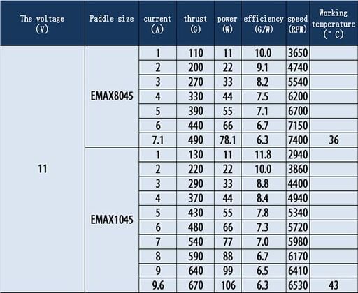
For a quadcopter to be designed, there are various factors that need to be addressed before the design process can begin. The first factor is the size of the quadcopter, as there are various sizes ranging from 4" quadcopters all the way to sizes greater than 12" quadcopters. Due to the requirements of this project and the necessity to carry an additional payload, a larger size quadcopter is required as it will produce more thrust to lift the additional payload. Because we are using the Emax MT2213 935KV motors, the manufacturer provides a chart for the maximum thrust each motor can produce depending on the size of the propeller, which is either an 8" or 10" propeller. These calculations can be seen below in Figure 2, where a 1045 propeller was used in this project due to the larger maximum thrust. These motors were chosen as they provided a large amount of power when paired with a 30A ESC as seen in Appendix 1 and Figure 2. The motors need to be powerful for this quadcopter in order to carry any additional payload the user mounts to it, and 935kV motors satisfy this requirement.

Looking at this chart, there are multiple different thrust values for a 1045 propeller. In order to determine the maximum value, the largest current is used to simulate the motors at full throttle, yielding a maximum thrust of 670g per motor. Because this is a quadcopter using 4 motors, the total thrust that the quadcopter can produce is 2,680g, which is double the combined weight of the frame, components, and payload. This value was used as one of the design criteria, as the total weight of the quadcopter and components needs to be less than this value to ensure that an additional payload can be carried, as the thrust to weight ratio needs to be greater than one based on the equation below2. The optimal value for the thrust to weight ratio is 2, as this value allows the quadcopter to hover at half throttle. This means that the quadcopter will be able to accelerate out of a hover to gain or lose altitude, as a thrust to weight ratio lower than 2 will limit the acceleration and possibly deny any gain in altitude.
Propeller clearances[edit | edit source]
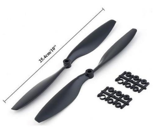
Because we are using a 1045 propeller, seen in Figure 3, the frame must be able to accommodate a 10" diameter at the end of each arm without interference with the other components. This is crucial as any interference will cause damage to both the frame and the components mounted on it. To adhere to all requirements of this project, the propellers will have a tight interference with the center body of the quadcopter, which will further reduce the overall size and weight, allowing for a heavier payload to be carried. Due to the motors being hard mounted to the frame, this tight tolerance can be held as the motors will not shift or torque during full throttle maneuvers.

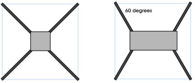
The shape of the frame design will also play a role in the clearances of the propellers. If the frame is too small, the propellers will interfere with each other during operation. Because of this, a minimum spacing of 10" between the rotational axis of the propellers and motors needs to be held, while a larger spacing is necessary to house the Arduino and additional components in the center of the quadcopter. Based on the research found in the References and Research Findings at the end of this report, it was determined that a square-cross shape frame design was ideal as it maximized the space in the center of the quadcopter and eliminated the need for additional stability components. The structural stability found using a square-cross shaped frame design is also much greater than a hybrid-X shaped quadcopter where the quadcopter's footprint is rectangular in shape compared to square in the case of a square-cross shaped frame design1-3,5,7.

Protection[edit | edit source]
The quadcopter must also be water-resistant as per the requirements stated previously. To do this, the Arduino, receiver, IMU, ESCs and camera board will be housed under a cover in the center of the quadcopter. This allows the quadcopter to be protected when it comes in contact with water from either landing or flying through different weather conditions. This cover will be slightly conical in order to provide the tight clearances with the propellers during flight.
The final protection design choice for this quadcopter is to raise the frame off the ground. This is done through feet mounted below the motors. These feet will allow the user to take off when the ground is wet or covered in debris without risk of damaging the components attached to the quadcopter. These feet also provide another purpose as they allow space between the bottom of the frame and the ground for mounting different equipment and payloads. In this project, the camera is mounted on the bottom of the quadcopter and is suspended above the ground due to the implementation of these feet on each corner. Because some payloads will be larger than others, the size of these feet will need to be easily changed by the user to adapt to different scenarios and purposes. The feet also provide a secondary purpose as they absorb much of the shock and force that is experienced form landing. The feet must be able to bend slightly during landing to reduce the displacement in the arms and prevent failure in other components of the frame.
Control[edit | edit source]
The quadcopter will be controlled using an Arduino Uno R3 using the open-source software MultiWii. This software can be used to control any aerial machine and is built specifically to reduce the complexity for the user. This software is open source and is built by the community and is constantly expanded to include new components and features, which will allow future users to easily add different equipment as payloads. In this project, the payload of a camera is added as an auxiliary input in the code and can be controlled using the handheld transmitter to record photos and video.