Abstract[edit | edit source]
This page gives brief overview of the design and development of a low cost circuit for extracting maximum power from the Solar panel and charging a storage battery optimally. The designed circuit consists of a microcontroller (PIC16F72) which generates high frequency pulse signal of different pulse width in accordance with the output of solar panel and electrical characteristics of the load to operate the system at maximum efficiency. The generated pulse signal drives a DC-DC Buck-Boost converter which gives constant voltage of 15V to the battery ensuring optimum energy being stored in the charging battery. The microcontroller controls the operation of the system according to the assembly language codes burned in it, which had been developed in MPLAB IDE. Microcontroller (PIC16F72) monitors the PV panel and battery conditions and generate required control signals to deliver maximum power to the battery irrespective of the output voltage of solar panel.
Background Study[edit | edit source]
There are several options for Maximum Power Tracking of PV system including incremental conductance, Fuzzy Logic Control, The DC-Link Capacitor Droop Control, Current Sweep technique, etc. [8] The DC-Link Capacitor Droop Control technique incorporates a boost converter in the topology. However, to ensure optimum charging of battery in both high and low insolation level, a Buck-Boost converter is needed. Design of most Buck-Boost converters requires multiple MOSFETs [7], [9] which consume a significant amount of power as switching loss. The inverting Buck-Boost converter in the proposed system constitutes of only one power MOSFET, [1], [6] which reduces the switching power loss. Another important aspect of Solar PV system is the charge controller. Charge Controllers block reverse current, prevent battery overcharge and over discharge. [10] The proposed system also integrates the function of charge controller through its dynamic microcontroller coordination.
Basic Operation[edit | edit source]

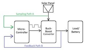
Below shows the basic block diagram of the MPPT system. To charge the storage battery at constant voltage, a DC-DC buck-boost converter is driven by the square pulse generated from the microcontroller. If output charging voltage to the battery is less than specified voltage, then duty cycle is increased by the microcontroller to raise the output voltage and vice-versa. The microcontroller senses output voltage of solar panel through path A. This sample is used to determine whether the MPPT system should deliver charging current to the battery or not. Feedback from the input of the battery received through feedback path B is used to customize the duty cycle of the pulse generated from the microcontroller such that the system get maximum possible power from PV panel to deliver the battery.
Devices and Components Used[edit | edit source]
The device and components used in the design are specified below: microcontroller (PIC16F72) P-channel MOSFET (IRF9530) p-n-p transistor (BC178) n-p-n power transistor (BD437) inductor resistors capacitors diode
Proposed System[edit | edit source]
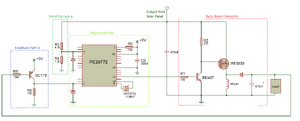
Our proposed system consists of the key units of sampling path, feedback path and the blocks as shown in Fig. 1. These are briefly discussed under the respective sub-headings. Detailed explanation is available in internship report. The detailed schematic diagram for the proposed system is illustrated in Fig. 2.

Buck-Boost Converter[edit | edit source]
The Buck-Boost Converter adjusts the voltage output form the Solar panel by either increasing or decreasing for charging the battery at the optimum voltage.
Sampling Path A[edit | edit source]
Sampling Path A is a simple voltage divider which scales the voltage from solar panel to low level (below 5V) appropriate for using as an input to microcontroller.
Feedback Path B[edit | edit source]
A simple voltage divider cannot be used in this feedback path as the scaling down of negative voltage would also produce negative voltage which is not suitable for using as an input to microcontroller. So, we used a low power p-n-p transistor (BC178) to invert and sample the voltage within the operating range of PIC microcontroller
Microcontroller[edit | edit source]
The microcontroller is the key unit of the system which compares input values with the pre-set values to customize the duty-cycle of the pulse signal to produce the required output. The input from sampling aath A is used to determine whether to keep the system running. In case of very low insolation solar panel does not provide significant energy so input from sampling path A goes below the threshold prompting the microcontroller to stop charging the battery. The input from feedback path B is used to alter the duty cycle of the pulse to buck-boost converter. If feedback is less than the target voltage, microcontroller increases the duty cycle of the pulse, which in turn increases the output from buck-boost converter. Similarly, if feedback exceeds target voltage the duty cycle is reduced.
Expiremental Finding and Discussion[edit | edit source]

Instead of solar panel, variable bench power supply has been used to vary the input of dc-dc converter voltage to examine the PWM wave with change of input voltage. Moreover, a dummy resistive load has been used instead of battery.
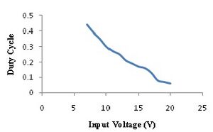
Fig. 3 shows experimental result of the duty cycle required to produce a fixed 15V output for various input voltages of the developed DC-DC converter.
The microcontroller adjusts the duty-cycle to produce 15V output. However, the Buck-Boost converter output cannot change as quickly as the microcontroller's change in duty-cycle in real time operation. It occurs due to the presence of power transistor in the MOSFET driver circuit; power transistor introduces a delay between its input from the microcontroller and output to MOSFET. So a suitable delay (0.63 second) is allowed at the end of each AD conversion to keep the Microcontroller and DC-DC Converter working in phase.
Moreover, due to large gate capacitance of MOSFET, it cannot be switched off quickly. As a result, if the duty cycle of the pulse signal is more than 0.44, the MOSFET is never switched off completely and hence the system does not works properly. Therefore, pulse width can only be changed within certain range (0.04-0.44) for the developed experimental model. The duty-cycle range might vary for other experimental models depending on the MOSFET used and the type of Buck-Boost Converter incorporated in the system.
Conclusion[edit | edit source]
The system consists of only one MOSFET reducing switching loss and component cost compared to other Maximum Power Extractor system. Operating dc-dc converter at high frequency facilitates use of small low cost inductor that further reduces resistive loss in the inductor. The developed system optimizes the power delivered to the battery even at low insolation level and increases the overall efficiency of Solar Power system.
Further Work[edit | edit source]
This design is a prototype designed in the Laboratory. Further research need to be carried on the efficiency testing and by integrating the design with a solar panel.
References[edit | edit source]
[1] D. W. Hart, Power Electronics, 1st ed. Valparaiso, Indiana: McGraw Hill, 2011 [2] (2014) Magnetics Website. [Online]. Available: http://www.mag-inc.com/design/design-guides/Inductor-Design-with-Magmetics-Ferrite-Cores [3] S. M. Azim, "Development of MPPT Circuit for Solar Panel," Brac University, Dhaka, Bangladesh, Intern. Rep.,2014. [4] "PIC16F72 data sheet," Microchip, Arizona, USA. [5] "PICmicro Mid-Range Reference Manual," Microchip, Arizona, USA. [6] N. Mohan, T. M. Undeland and W. P. Robbins, Power Electronics, 2nd ed., Minneapolis, Minnesota: John Wiley & Sons, Inc. 1995 [7] B. Sahu and G. A. Rincon-Mora, "A low voltage, dynamic, noninverting, synchronous buck-boost converter for portable applications," in IEEE Transactions on Power Electronics, vol.19, no.2, pp.443,452, March 2004 [8] T. Esram and P. L. Chapman, "Comparison of Photovoltaic Array Maximum Power Pont Tracking Techniques," in IEEE Transactions on Energy Conversion, vol.22, no. 2, pp.439,449, June 2007 [9] L. Chang, Z. Liu, Y. Xue and Z. Guo "A Novel Buck Boost Inverter for Photovoltaic Systems," in Canadian Solar Buildings Conference, pp.1,8, August 2004 [10] (2015) Blue Sky Energy Website [Online]. Available: http://www.blueskyenergyinc.com/reviews/article/what_is_a_charge_controller