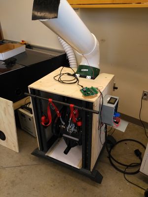
This project was developed mainly by Walker Nelson Peter Gorecki, who finished their capstone design project through Michigan Technological University in 2016. Since its publishing, the Granulator design and assembly itself has not changed, but information regarding the power consumption while granulating different thermoplastics has been researched.
This Wiki page contains a link to the website where the project files and initial description are hosted, and updates for this project for the future.
All relevant files[edit | edit source]
As said in the Background and Introduction; all original files (CAD, construction, report, simulation) can be accessed on this site *plastic granulator
Files relating to power consumption, or noise reduction are located on this page
Fall 2019[edit | edit source]
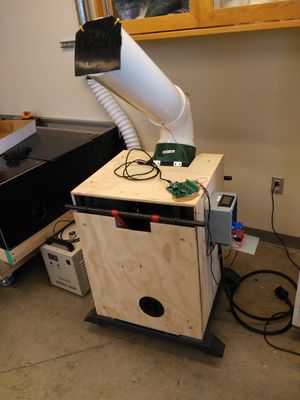
After feedback on the design, we will be redesigning portions of the granulator to improve the machine's efficiency. The main change we will be looking at making will to have a pipe that encloses the granulation blades for 270 degrees of rotation. Other improvements such as particle collection, material change over and hopefully increase the material capabilities.
Spring 2019[edit | edit source]
Work done on the Granulator MK II in the spring semester of 2019 can be accredited to Sean Scsavnicki, Arvind Ravindran. Faculty who aided this project during this time include Shane Oberlier, Dr. Pearce, and Paul Fraley.
Power Consumption[edit | edit source]
With the aid of Shane Oberlier, an open-source printed circuit board and arduino nano were attached to the power supply to measure the power output of the granulator MKII while it was processing different materials. During each of the power recording sessions, thermoplastic was inserted at a rate the granulator MKII can handle. This rate is not measured, as it highly depends on the geometry and density of the inserted plastic.
This data was processed and its results appear below in a table
| PLA (Polylactic Acid) | PETE (Polyethylene terephthalate) | |
|---|---|---|
| Average power consumption | 403.6488 W | 383.9109 W |
Noise Reduction[edit | edit source]
Recently, noise has been a big concern of the granulator MKII owing to the needs of power consumption and safety. To enhance adoption of the granulator by more people, it was decided to undertake noise control measures and make the device operate with reasonable noise tolerance.
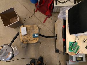
Tests were performed to find the sound pressure levels of the granulator MKII system including the auxiliary devices such as the vacuum pump. It was determined that the vacuum pump was the loudest source with a distinct 250 Hz octave band frequency wherein the levels were significantly higher. Panel gaps in the enclosure for the granulator provides leakage paths for the sound and hence it was decided to seal these gaps appropriately. The inner lining of the walls were packed with foam to increase transmission loss between the source and the surrounding.
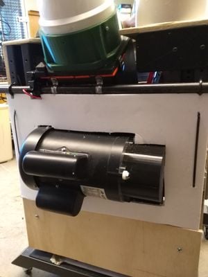
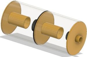
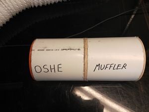
Using the sound data that was collected, dimensions were found for an expansion chamber that could be attached to the 5-gallon bucket shop vacuum, and a 3D model was produced to utilize the leftover PVC and a 3D printer. The CAD file is linked here, and the construction of the expansion chamber is described in this section. As 250Hz was the chosen frequency band for attenuation, the double tuned expansion chamber design was chosen as it provides good transmission loss around the frequency of interest while having good attenuation around the octave bands as well. However, the muffler aids in low frequency attenuation and by lining the inner walls of the muffler with fiberglass foam, we can achieve in higher frequency range as well.

Construction[edit | edit source]
Start by printing these four files, one of which (Middle_1_2x) must be printed twice as it is used twice, and cut two 8.7122 inch sections from the schedule 40 6" ID PVC used in the construction of the granulator. You will need some 1.5" or less thick fiberglass insulation as well and a hot glue gun.
Once everything is cut and printed start assembling the expansion chamber. First, get the Inside_half_of_Vacuum_half and glue it to the middle of the flat part of the Vacuum_half. Next, glue this onto one of the pipe segments with the smaller hole facing out. Next, insert the fiberglass insulation inside the chamber. To finish the first half, glue one Middle_1_2x with the long bit facing towards the inside of the chamber.
To start the second half, glue in the Middle_2 on the other pipe section, with the tube part facing inside and use fiberglass insulation to fill the inside around the walls. To finish the second half, glue in the other Middle_1_2x with the tube facing inside the chamber.
To complete the expansion chamber, glue both parts together, where the Middle_2 is matched with the Middle_1_2x on the first one.
File:Inside half of Vacuum half.SCAD
The modifications to the granulator were verified with sound level measurements and the following results were found:
1) Compared to the earlier design, a 4dB overall reduction in sound levels was achieved with attenuation at the 250Hz band particularly.
2) As the focus of the noise reduction was concentrated towards the vacuum, 5 dB reduction was achieved here.
3) Only marginal reduction in the granulator noise levels were achieved and this was possibly due to existing panel gaps in the enclosure. They were not sealed off due to ease of access.
Suggestions for Improvement[edit | edit source]
1) Higher levels of attenuation could've been achieved through the muffler but while testing, it was observed that the top portion of the vacuum had leakage paths for the sound. A trial was performed with attaching foam over the vacuum to understand attenuation levels and the levels did drop significantly (around 8 dB). However, one must balance the needs for heat ventilation with sound proofing to ensure integrity of the vacuum working is not affected.
2) Plugging the panel gaps also improved the sound attenuation levels (about 3 dB) when a trial was performed to ascertain this.
Modal Analysis of Granulator[edit | edit source]
Modal analysis of granulator was performed using FEA (Ansys Workbench R19.1) to find mode shapes and natural frequencies.
It was found that mode 1 occurred at 24.6 Hz from the analysis while the motor of the granulator operates at 12.5 Hz currently which is at a reasonable tolerance away.
This analysis was done to confirm that the granulator was not undergoing resonance as that would worsen the noise levels experienced.
Potential for recycling common thermoplastics[edit | edit source]
Intro[edit | edit source]
This semester the OSHE has teamed up with the sustainability enterprise and sustainability house to attempt to create house numbers from recycling thermoplastics, mainly PETE, or #1 recycling. The results of this project are presented in this section.
Sustainability house collaboration[edit | edit source]
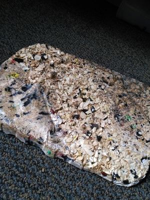
Each piece of PETE plastic was cleaned, and then cut into small pieces (around the size of a hand) to be put into the granulator. From our observations, it takes around 3 hours to get a kilogram out of the machine. We believe that the lack of efficiency in granulating PETE comes from its flat geometry. The granulator, as stated in the original report, uses shearing as its main cutting process. Because the pieces were so thin, the member simply deflects out of the way of the spinning blades instead of being cut to size. If we were to make a suggestion, it would be that this type of grinding/granulating machine should not be used for thin PETE members. Other grinder/granulating machines should be used if efficiency is desired.
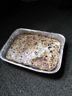
After the pieces were cut up and brought down to size, Paul Fraley from the MTU materials science & engineering department allowed us to melt the plastic in a furnace housed by their facility. The plastic was melted in a 8.5" x 12" baking pan, and did not turn out to a quality that should be machined. The melted plastic is far to brittle, and it failed to melt entirely through. This plastic is also very hard to melt, as a furnace would have to reach past 500 degrees Fahrenheit or 260 degrees Celsius.
The project is considered failed for now, but if it is further investigated by the open source hardware enterprise, in the form of attempting to remelt the plastic, or changing the material properties of the sheet.