
CPH Library Hall of Simulation wind tunnel 2026
.png)
| Type | |
|---|---|
| Authors | Tommaso Magnaghi Peter Valerio Jose Padilla Joshua Turner |
| Location | Arcata, California, United States |
| Status | In progress |
| Years | |
| Made | Yes |
| Replicated | No |
| Uses | education, science |
| Map | |
|---|---|
| Location | Arcata, California, United States |
| Coordinates | 40.876° N, 124.079° W |
The Wind Tunnel is a project created to show lift and the application of winds at high speeds. Created by team meCanopy consisting of Tommaso Magnaghi, Jose Padilla, Joshua Turner and Peter Valerio in Spring of 2026 for Engineering 205: Intro to Design. The project was created for, and can be found at the second floor of the Cal Poly Humboldt Library in the hall of simulation as a way to increase the interactivity and engagment from learning.
Background
[edit | edit source]This project has been requested by the Cal Poly Humboldt Library, the Dean of Libraries at Cal Poly Humboldt and representative for the library, Mr. Oberlander has expressed a desire for a more interactive learning experience, and as such, has commissioned multiple projects including the Wind Tunnel to be put in the library. The wind tunnel project, if successful, will be replacing the previous iteration and is being developed by team meCanopy consisting of Tommaso Magnaghi, Jose Padilla, Joshua Turner, and Peter Valerio of the Spring 2026 Engineering 205 class at Cal Poly Humboldt.
Problem statement
[edit | edit source]The objective of this project is to create a high quality Wind Tunnel for the Cal Poly Humboldt Library that will last 10 years without breaking and that gives those who interact with it a basic understanding of lift, an important aerodynamics concept.
Criteria
[edit | edit source]| Criteria | Description | Weight (1-10) |
|---|---|---|
| Maintainablity | How long the Wind Tunnel will last and how easy it will be to keep it running smoothly. | 10 |
| Presentation | How visually appealing the Wind Tunnel is. | 10 |
| Educational | How much people learn from using the Wind Tunnel. | 10 |
| Interactivity | How much people are able to interact with the Wind Tunnel, | 9 |
| Cost | How expensive the Wind Tunnel is. | 8 |
| Noise | How loud the Wind Tunnel is because it is in the library | 7 |
| Adaptability | How changeble is the Wind Tunnel (parts, tested object within the tunnel). | 6 |
| Portability | How movable and portable the Wind Tunnel is. | 6 |
Prototyping
[edit | edit source]The first prototype was a simple cardboard assembly of the wind tunnel. The cardboard was used to model the space and how the wind tunnel would end up physically as shown in figure 2. The model was good for developing the physical dimensions of the end product but it didnt let us test anything mechanical so we moved on to our next prototype.
The second prototype was a smaller tunnel centered around a 120mm pc fan to be more of a proof of concepet for the method of vidual aid. The tunnel had a small plane inside attached to the wind tunnel with string so when the fan was turned on the plane would rise and glide. This prototype worked to show the plane would lift but it was inconsistent and turbulant.
The third and final protype was an early iteration of the wind tunnel. The goal of this prototype was to test main construction. The initial design shown in figure 3 was completely smooth on the outside which forced the use of chemical fastening which would lead to an unsecure seal and would leave gaps on the outside of the Tunnel. This forced a change of having outisde ridges for mechanical fastening. This along with the other two prototypes gave us the information needed for final construction.
- Prototyping Gallery
-
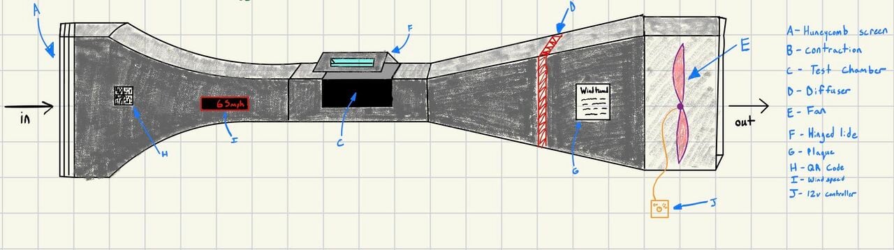 Figure 1-This image depicts a early sketch trying to put imagination to paper.
 -
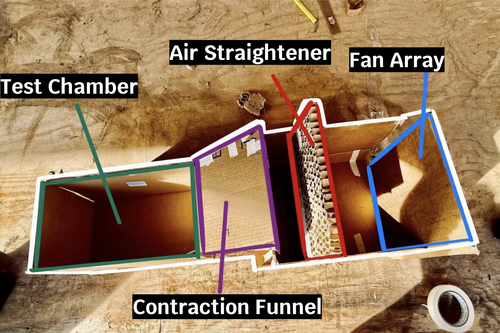 Figure 2- This image depicts our earliest prototype giving us a size estimate for the client.
 -
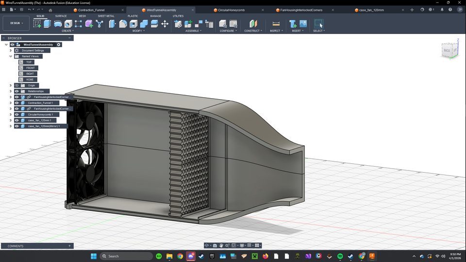 Figure 3- This image depicts a 3d render in CAD during the development for 3d printing.


Final product
[edit | edit source]
The wind tunnel is composed of five main sections. These are further subdivided into quarter sections for ease in 3D printing. Starting at the inlet section where the fans reside. This section contains the quad 120mm fan array. Following the air path the next section bolts up is the air straightener. The choppy wind produced by the fan array gets forced through in an orderly fashion. Further down is the mesh screen that bolts in. This is used to give uniform air speed across the area of the interior. The corrected airflow immediately enters the contraction funnel where it is accelerated. The tunnels curvature was calculated using a fifth order polynomial equation in which it takes the 235mm diameter of the fan array and condenses it to 105mm in order to accelerate air speed for lift generation. Finally, we have the test chamber where the demonstration airplane is tethered to the inner corners of the chamber. The entire 3D printed assembly is fastened together with silver 4M bolts and nuts.
Construction
[edit | edit source]
The construction of our wind tunnel was a carefully planned and methodically executed project, ensuring precision and durability at every stage. The process began with the 3D printing of all 17 components, each designed to fit together seamlessly. These Parts were then assembled with attention to detail using 4mm screws, ratchets, a socket wrench and a 7mm boxed wrench to guarantee a secure and stable fit. The assembly required patience and precision as each piece had to align perfectly to form the structural integrity of the wind tunnel.
Once the framework was complete, we moved on to installing the four 120mm fans, each secured with four fan brackets. These fans were paired with the air straighteners to ensure the airflow generated was smooth, consistent and free of turbulence followed by the mesh to distribute the air. To provide precise control over the wind speed we integrated a wind speed controller directly connected to the fans allowing for adjustable airflow during testing.
For enhanced visibility and observation, we custom fabricated a Plexiglass window for the test chamber. Using a laser cutter, we precisely cut out two pieces of plexiglass, each measuring by 11.5X.7.5 inches to fit the designated opening. This window provided a clear view of the interior making it easier to observe the aerodynamic effects in real time.
Inside the test chamber we placed a miniature plane to visually demonstrate the principles of air flow and aerodynamic lift. As the fans generated wind the plane's response rising and maintaining lift served as a tangible validation of the Wind tunnel's functionality and making science fun for all that counter it. The successful demonstration not only showcased the effectiveness of the setup but also left the library staff impressed with project's results.

Video instructions
[edit | edit source]This is a video on what you need to do to assemble the meCanopy wind tunnel. It will show you what is involved with assembly such as where and how to install fasteners. How the fans get assembled. How to install the air diffusers. Where to get CAD files. Even how to use it. This video contains clips captured during assembly with a voiceover. - https://drive.google.com/file/d/1IzRdx4mJ5uOlpTixCaqWZnjDxVI6f_by/view?usp=sharing
Bill of materials
[edit | edit source]Description of costs, donations, the fact that this is just proposed, etc. For a simple cost table, see Help:Table examples#Cost Table and Template:Bill of materials for two nice formats.
| Item | Amount | Cost per unit | Total |
|---|---|---|---|
| 120mm Fans(5 pieces) — https://www.amazon.com/Printer-Filament-SUNLU-Dimensional-Accuracy/dp/B07XG3RM58 | 1 | USD 34.99 | USD 34.99 |
| PLA Fillament — https://www.amazon.com/Printer-Filament-SUNLU-Dimensional-Accuracy/dp/B07XG3RM58 | 4 | USD 13.99 | USD 55.96 |
| Fan Speed Controller — https://www.amazon.com/Controller-100-240V-Adjustable-Splitter-Connector/dp/B0D78FGVJL | 1 | USD 14.99 | USD 14.99 |
| Fan Guard (4 Pieces) — https://www.amazon.com/dp/B07VCNLQZD | 1 | USD 5.99 | USD 5.99 |
| Box of 4x12mm Bolts — Ace Hardware | 1 | USD 24.99 | USD 24.99 |
| Box of 4mm Nuts — Ace Hardware | 1 | USD 7.99 | USD 7.99 |
| Plexiglass Sheet — Donated by library | 2 | USD 0.00 | USD 0.00 |
| Mesh — Donated by team | 1 | USD 0.00 | USD 0.00 |
| 4x25mm Bolts — Ace Hardware | 4 | USD 0.65 | USD 2.60 |
| Grand total | USD 147.51EUR 126.86 <br />GBP 107.68 <br />CAD 182.91 <br />MXN 3,075.58 <br />INR 11,041.12 <br /> | ||
Operation
[edit | edit source]Maintenance
[edit | edit source]Maintenance of the wind tunnel is fairly straightforward. The most important task is making sure it is off when not in use in order to save on power. Maintenance will be solely dusting unless something breaks which can be done by any library staff. We recommend using compressed air. Two of the top quarters of the tunnel should be opened up for a more detailed cleaning once a year. It is detailed in the instructional video how to access the interior. Parts may be replaced as needed by someone with a more technical background with 3D printing operation knowledge. The maintenance schedule is outlined below.
Maintenance schedule
[edit | edit source]This is when to maintain what. Please keep the format the same as it populates the kiosk in CCAT.
- Daily
- Make sure the fans are off, nightly
- Is the plane still attached?
- Weekly
- N/A
- Monthly
- Dust off the outside and easily accessible areas of the wind tunnel
- Yearly
- Disassemble the wind tunnel and dust the internal components
- Every 6 years
- The warranty life span of the fans are up. Replace for reliable use.
Conclusion
[edit | edit source]Testing results
[edit | edit source]Our testing of the final product allowed us to add a flying plane as the visual medium as oposed to a stationary object with tinsel or another type of visual medium.
Discussion
[edit | edit source]Testing was conducted by 3d printing different planes with varrying material, size, shape and infill. We made various holes at different parts of the planes and tied them to string attached to varying parts of the wind tunnel to try different orientations. After many iterations we managed to get one working by putting wholes in the top middle of the wings and one on the back center of the main body.
Lessons learned
[edit | edit source]Next time we would start prototyping on a smaller scale with similar materials so we can learn if the main body needs to be adjusted and also start building earlier so we could have more time for testing and troublshooting the visual medium.
Next steps
[edit | edit source]Some next steps to take would be doing some upgrades to the wind tunnel. One possibility is to add another form of visual medium like water vapor or gas for a different experience or another possibilty is adding another piece to the wind tunnel that slows down the air once it exits the main chamber to prevent wind blowing out of the end.
Troubleshooting
[edit | edit source]| Problem | Suggestion |
|---|---|
| Plane doesn't fly | Make sure the plane is in the correct spot and make sure it is on |
| Does not turn on | Make sure it is plugged in |
| Low airflow |
|
Team
[edit | edit source]- Tommaso Magnaghi
- Jose Padilla
- Joshua Turner
- Peter Valerio
- ENGR 205 Spring 2026
References
[edit | edit source]
| Authors | |
|---|---|
| License | CC-BY-SA-4.0 |
| Organizations | Cal Poly Humboldt |
| Cite as | Lonny, Tommaso Magnaghi, Peter V, ElOnionWaPo (2026). "CPH Library Hall of Simulation wind tunnel 2026". Appropedia. Retrieved July 9, 2026. |