
CPH Library Hall of Simulation LED wall

| Type | |
|---|---|
| Authors | BoldMoldMarch Jjt79 David Wildman |
| Location | Arcata, California, United States |
| Status | Deployed |
| Years | |
| Made | Yes |
| Replicated | No |
| Uses | education, science |
| Map | |
|---|---|
| Location | Cal Poly Humboldt, Arcata, United States |
| Coordinates |
The LED Flexible Wall is a project created by Sam's Sons, a team from Cal Poly Humboldt's (CPH) ENGR 205 Introduction to Design class. This LED wall uses WLED, an addressable LED software that controls an LED array by changing its color, patterns, and uploading images. This project was worked on from February 2026 to May 2026. The LED wall was created for the CPH Library's Hall of Simulation in order to increase student collaboration with each other by creating an engaging environment for them to study in.
Background
[edit | edit source]Sam's Sons is a team of engineering students from Cal Poly Humboldt's (CPH) ENGR 205 Introduction to Design class. For the Spring 2026 semester, we created a flexible LED wall that people could interact with in the Hall of Simulation in the CPH Library. The Hall of Simulation is a project initiated by the CPH Library in order to encourage learning by doing and inspiring younger people to pursue a higher education. The LED wall was completed in May 2026 over a 12 week timespan, including meetings with our client representative, Library Dean Cyril Oberlander. Our planned budget for this project was $425.
Problem statement
[edit | edit source]The objective of this project was to help the Library turn the Hall of Simulation and other collaborative spaces into a more interactive and inspiring place for students and visitors alike. Using the LED wall, users can flex the screen into various shapes, display colors, patterns, text, and images using the WLED app or a WLED web link. The LED wall allows users to create a more comfortable and immersive environment around them that enhances their mood and makes for a place where students can study better.
Criteria
[edit | edit source]Based on the goals of this project and the client specifications, these were the following criteria that was important to the client and for us to consider while designing the project.
| Criteria | Description | Weight (1-10) |
|---|---|---|
| Maintainability | Maintenance and part replacement is minimal | 9 |
| Durability | The LED wall is as durable as the rolling whiteboards in the CPH Library | 8 |
| Ease of Use | Students and staff can execute any task within 10 minutes | 8 |
| Aesthetics | Users feel that they are welcome to use the wall; they are not dissuaded by the wall’s appearance | 8 |
| Cost | Under $425 | 4 |
Prototyping (The start of each image name should be "Sam's_Sons_...")
[edit | edit source]Some of our most important discoveries happened during the prototyping process. The sections below discuss these findings by each part of the project.
LEDs
[edit | edit source]The LED system is one of the most important parts as they are the primary influence of the wall's aesthetics, and important criteria for this project. Initially, we were going to use LEDs with a 60LED/m density, but we realized that the costs of using these LEDs were too much for our assigned budget of $425. We settled on WS2812B ECO LED strips from BTF Lighting because of their reputation within the WLED community and because of how cheap they were. Costs also influenced why we used 5V LEDs for our system.
For the control system, our initial choice was influenced by a YouTube video that our client representative, Cyril Oberlander and instructor, Lonny Grafman, had shown us. His solution uses multiple ESP-32 microcontrollers that would communicate with each other on their own network, and these controllers would all be running through the FastLED package for Arduino. For our initial test, we wanted to use an Arduino UNO R4 with FastLED to ensure that all of our LEDs could work. While it did work. We also realized that using FastLED would not be user-friendly, something that our client specified explicitly. Because of FastLED's high learning curve, we decided to use WLED for our solution.
Our solution required a WLED-compatible ESP-32-based microcontroller. We initially used an ESP-32 microcontroller made by BTF Lighting that also contains a microphone for noise-controlled activation. However, talking to the WLED community and local experts, we discovered that we needed more data ports due to voltage drop, a phenomena where electricity flowing through a wire is lost through heat. These referrals led us to the QuinLED Dig-Octa system, a board created by Quinndor that has two boards, one that manages data, and one that manages power.
- LED Wall Prototyping Process
-
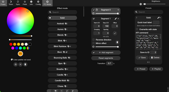 WLED Software
 -
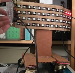 The LEDs being operated by FastLED and an Arduino R4 Minima
 -
 The LED controller that Sam's Sons initially wanted to use for the flexible LED wall
 -
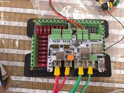 The QuinLED-Dig-Octa System that Sam's Sons ended up using for their flexible LED wall
 -
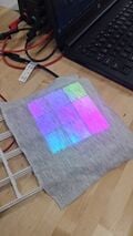 The final product, in small-scale. This is what we expect our flexible LED wall to look like at the end


Flexibility
[edit | edit source]Because a big appeal of the LED wall is that it can be flexed into various shapes, understanding what materials did and did not work through numerous prototypes was a key part of developing a working final product. The way we chose to make the screen flexible was through the use of a bending medium that would hold its shape when bent and could be bent back if desired. The bending medium (hardware cloth in out case) was then wrapped in some material that would electrically isolate the LEDs from the hardware cloth and act as the main attachment point for other components such as LEDs, flexible grids, and the diffusion cloth. We chose this design because it was simple in principle and the bending medium was readily available. However, numerous issues arose during prototyping because of the nature of some materials and poor design choices.
One of the first major hurdles that was encountered was designing a flexible grid that could be printed in mass quantities, use as little material as possible, space the LEDs away from the diffusion cloth, and properly separate the light coming from the LEDs into their own "cells" so to speak. The first version of this grid used far too much material for a single unit and proved to be inflexible for someone to reasonably bend. This issue was solved by optimizing the design of the flexible grids by remodeling the grids and comparing their cost in materials per unit compared to how effectively they could bend (see Figure 1). In the end the cost of materials per unit went down by approximately 60% and the grids were far more flexible compared to their predecessors.
The next issue experienced with the flexible grids is how to attach the diffusion cloth in such a way as to prevent wrinkling within the cloth to give a more pleasing appearance. During initial testing, even using a stretchable fabric wrinkled when the grids were bent in such a way as to make the fabric contract. An alternative solution was tested where a non-stretchable fabric would be glued in such a way as to not stretch or contract when the flexible grid was bent in any direction. This solution proved to be infeasible due to the challenges experienced in assembling, the mounting of the cloth being the direct cause of permanent warping observed in the flexible grids after assembly, and how this design was not effective at preventing the initial problem (see Figures 2 and 3). In the end, fabric wrinkling with stretchable fabric was seen as an inevitable problem that could not be fixed without extensive research and testing into other solutions.
Another issue arose when the flexible grids were tested in conjunction with the LEDs in order to test whether or not the spacing between the LEDs and diffusion was enough to evenly diffuse the light from the LEDs. However, testing showed that the height of the flexible grids was insufficient to evenly distribute the light from the LEDs (see Figure 4). Increasing the height of the grids helped, but this caused issues in the ability of the grids to limit bending in the direction the grids were placed, causing them to buckle and leave the bending medium vulnerable to breaking (see Figure 5). Other alternative solutions were tried, such as making bend limiters made of solid material (see Figure 6). However these proved to be problematic because they did not properly adhere to the covering of the bending medium. In the end, thickening the walls of the flexible grids and adding another, shorter one onto the back proved to be an effective solution to prevent sharp bends in both directions and lets the light from the LEDs properly diffuse (see Figure 7).
The last major issue arose when considering a suitable material to cover the hardware cloth in order to give other components a place to stick, since hardware cloth has too little surface area for components to adhere properly. Plastic sheeting was the first material researched as the material used for the covering, however traditional means of adhering the plastic sheeting such as glue and fasteners proved futile due to the minimal surface area of the hardware cloth and the flexibility of the plastic sheeting. The only technique that was proved to be effective was shrink wrapping the plastic by first sealing the edges of the plastic hanging off of the hardware cloth and then heating the plastic over the hardware cloth in order to have a smooth finish. In prototyping, this design proved to be a very suitable option for our final product since it was easily accessible and was able to be attached to other components through the use of a superglue (see Figure 8). The issue is when using this technique on our final product, the forces the plastic exerted on the ends of the bending medium due to the plastic cooling and contracting became so great that the bending medium became warped and unusable for the final product (see Figure 9). This necessitated using a new material to overcome these issues. The material used in our product was packing tape, which worked in being able to wrap around the entire bending medium and be shrink wrapped to give a smooth finish. However, because packing tape is generally made from polypropylene or similar material and is thinner relative to other plastic sheets, only specialized adhesives with primers are able to bond the flexible grids to the packing tape effectively enough to be in a usable product. For future reproduction of this product, packing tape is not recommended due to the difficulty of adhesion experienced.
- Flexibility Prototyping Process
-
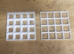 Figure 1: Comparison between the first flexible grid and the iterated version.
 -
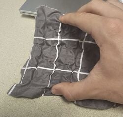 Figure 2: Front view of diffusion cloth on flexible grid.
 -
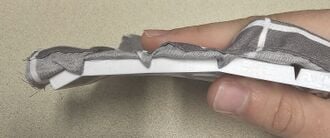 Figure 3: Side view of flexible grid with diffusion cloth.
 -
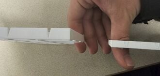 Figure 4: Difference in height between old and new grids.
 -
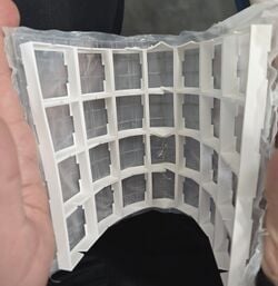 Figure 5: Flexible grid buckling under sharper bends.
 -
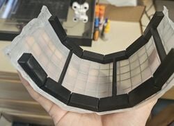 Figure 6: One of the alternative designs tested.
 -
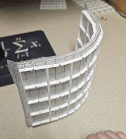 Figure 7: Final design that Sam's Sons settled on.
 -
 Figure 8: Prototype of shrink wrapping hardware cloth.
 -
 Figure 9: Implementation of shrink wrapping in final product.


Structural
[edit | edit source]The structural portion of this project important in order to keep the LED wall portable and easy to use for the average user. It involves designing a stand that is able to hold up the electrical components of the LED wall and the screen itself. This allows us to make the LED wall easy to wheel around to different rooms for the average user. However, we had a few iterations of what this stand would look like and how it would connect to the LED wall.
The first design for the stand involved a single pole that would hold up the entire screen and hold all of the electronics close to the bottom of the stand base to lower the center of mass in order to make tipping over the screen more difficult. Initially, we planned to design and make our own stand from scratch, however this proved to be a fruitless effort because of the time it would take to design a stable project using only one pole to prop it up would be impractical. This is why we chose to use medical stands that were bought at a scrapyard (see Figure 1). Medical stands proved to be the correct choice in our project because of their low cost, time to develop, and because medical stands are already designed to be hard to tip. However, because the screen was so long and the possibility that someone could use it to rest their arm on accident, the potential for tipping due to the force created by someone's hand pushing down could not be ignored (see Figure 2). Which lead to the one stand idea being abandoned in favor of two stands. Two stands allowed us to keep the flexibility that the one stand idea provided while making the LED wall more stable against people leaning on it (see Figure 3).
Another key part of the structural part of this project is figuring out how to connect the screen to the stands themselves. This problem was initially ignored until it became urgent enough to be tested. The first (and current) design being tested and used involves a clamping style bracket that clamps down on the hardware cloth in order to fasten the hardware cloth and hold it still. The bracket comes with two parts, the first being the back panel that attaches to the stands and the second being the bracket that goes on the front of the screen and includes 4 nuts to accommodate bolts that would clamp down on the hardware cloth when the bolts are tightened. The first prototype that was tested demonstrated that this design could indeed work to hold up the LED screen (see Figure 4). However the main issue with this design is that the bracket on the front of the screen occupies the same space that the flexible grids would have otherwise taken up. Minimizing this issue requires optimal bracket design in order to be as thin as possible and remodeling the grids in such a way that they do not need to occupy the same space as the brackets.
- Structural Prototyping Process
-
 Figure 1: Medical stand used in our project.
 -
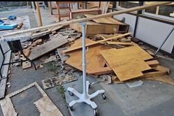 Figure 2: One stand design being tested by leaning on a wooden plank.
 -
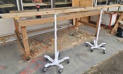 Figure 3: Two stand design being tested in the same way as the first.
 -
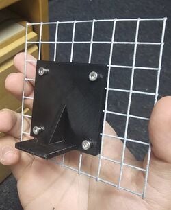 Figure 4: Prototype of the clamping style bracket being tested.


Final product
[edit | edit source]Overview
[edit | edit source]The flexible LED wall contains three main components: the electronics of the LED wall is what powers all of the LEDs and allows a user to control the LEDs with ease. The flexibility involves the flexible components of our screen. And the structure involves how all of these components are implemented to form one cohesive product.
Electronics
[edit | edit source]The LED wall itself uses 5 volt WS2812B based addressable LED strips. Both the data lines and power lines of the LED wall are connected in series and in parallel but in different configurations. For power, every LED is connected in series to power, with extra power injections placed throughout the center of the screen. For data, there are multiple data lines that control different parts of the LED screen but only one data cable is needed to control several hundred LEDs. These strips are powered and controlled by the QuinLED Dig Octa Powerboard and Brainboard respectively. And the source of the power comes from a MeanWell LRS 350-5 power supply, which connects to your power outlet.
Flexibility
[edit | edit source]Flexibility of certain portions of the LED screen is achieved by only using flexible or stretchable materials. The center of the screen holds a layer of hardware cloth that serves as the screen's source of rigidity and allows users to flex the screen however they want while holding its shape. The next layer is any thin material that is able to electrically isolate the hardware cloth from the LEDs and serve as a place to stick other components to. In our case polypropylene based tape was used, however this is not a good idea since polypropylene is difficult to adhere to. After the cover layer is added, the LEDs are added and soldered together. The next layer consists of flexible or inflexible grids that serve to distance the LEDs from the diffusion cloth and serve as bend limiters in order to prevent an end user from bending the screen too sharply. Flexible grids are used in flexible portions of the screen and are meant to be put on both sides in order to prevent sharp bends in both directions. Parts that are meant to be inflexible only need one grid to prevent flexing. The last layer is only necessary on the side or sides that contain LEDs. The diffusion cloth layer serves to diffuse the light coming from the LEDs to give a more user friendly experience.
Structure
[edit | edit source]The main part of the structure contains two medical stands that serve to add as much weight to the bottom as possible while also making it impossible to top over the screen when it is leaned on. The two stands are connected by a wooden plank which is bolted onto the medical stands. The wooden plank is also where the Dig Octa boards are stored in an ammo box serving as the enclosure. The stand connects to the LED screen by using a two part bracket. One part is bolted to the medical stands and the other is embedded inside the LED screen and contains nuts in order to be able to bolt onto the stand.
Construction
[edit | edit source]Instructions
[edit | edit source]This section was purposely written vague because Sam's Sons acknowledges that this project is a pilot program. The decisions made are not concrete, allowing the instructions to be more as documentation for how Sam's Sons created their LED wall rather than a strict checklist to follow. As long as you buy the parts that start each list, a user can create their own flexible LED wall.
LED Wall Panel
[edit | edit source]This component requires the following items:
- Chicken Wire or Hardware Cloth (as a flexible medium)
- Packing Tape
- TPU Filament (for 3D printing custom grids)
- Addressable RGB Strips (such as from BTF Lighting)
This component requires the following tools:
- Wire Cutters
- 3D Printer
Cut your flexible medium with wire cutters into a large sheet. In our case, it a sheet of hardware cloth with 1/2" square holes, that was 6.5' wide and 3' tall. Wrap this medium in packing tape. Be careful that your flexible medium is flat, as this can affect the overall aesthetics of your wall later. When you are done, calculate the amount of grids (W x H) that you need (we needed ____) and start printing that amount of grids. This may take a while, which is why it is necessary to do this step now. Make sure that you print equal numbers of both types of grids as they ensure that the LED wall will not snap due to extreme bend angles.
When this is complete, attach one strip of LEDs to the short side of your wall. This will serve as an alignment guide to make sure that other strips on the wall are evenly spaced. Grab a roll of LEDs and notice the arrow that runs on the middle of the LED strip. This is important as it shows the direction in which data runs along the LED strip. Also take note of the voltage of your LEDs. Now, cut and adhere one LED strip of appropriate length onto the LED wall. Repeat this step, ensuring that you pay attention to the direction of the wire. The best way to do this is to have the arrows moving in alternate directions to create a serpentine grid.
Electronics
[edit | edit source]This component requires the following items:
- WS2812B based LED strips
- ESP32 based controller for LEDs
- Power supply for LEDs and controller
- 18 AWG wire
- Enclosure
This component requires the following tools:
- Soldering Iron
- Screwdriver
The flexible LED wall uses an LED controller to control the LEDs. This controller needs to be ESP-32-based[1] to interface with WS-type LEDs. Ensure that the controller that you are using has enough data ports to run the LEDs that you are using. Each data port can run around ~600 LEDs comfortably.[2] Note the data pins that control your LEDs and other accessories as this can save a lot of time if troubleshooting an LED wall.
Using a soldering iron, use wires to solder connections in between strips. This allows strips in series to communicate with each other. To start a data connection, as the controller will be a separate structure from the LED wall itself, use a long wire in case that allows for leeway when deciding where you put your controller and power supply. LEDs will suffer from voltage drop, the phenomena where electric potential is lost when running through a conductor.[3] For a power injection, more commonly known as a path in a parallel circuit, the best place to wire these are at the center of the display. This allows power injection cables to rest on the rigid portion of the LED wall, preventing potential reliability issues resulting from flexing the LED wall. For all of our wiring, we used 18AWG wire.
Take note of the voltage of your LED strips and buy an appropriate power supply for your LED wall. We used WS2812B ECOs that run on 5V, so we bought a Mean Well LRS-350-5 AC-DC power supply. Mean Well is considered a reputable brand within the addressable light community. This power supply will need to be placed in an enclosure as it contains a live, exposed AC connection that can seriously injure or kill a user. The controller may also have to be placed in this enclosure because it may contain dangerous electrical components, such as a capacitor. This was the case with our controller as it contains two 1500uF 35V capacitors.[4] Be sure that your electrical enclosure box contains proper air flow for your power supply as overheating of the power supply can damage the enclosure and poses as a major safety risk.
Structure
[edit | edit source]This component requires the following items:
This component requires the following tools:
Bill of materials
[edit | edit source]Description of costs, donations, the fact that this is just proposed, etc.
| Item | Amount | Cost per unit | Total |
|---|---|---|---|
| LED Strips (5m, 30/m) — Donated, buy at https://www.amazon.com/BTF-LIGHTING-Individual-Addressable-300Pixels-Non-Waterproof/dp/B088BB8WTZ | 17 | USD 0.00 | USD 0.00 |
| WLED Controller — Buy at https://www.amazon.com/dp/B0FB38FDCS | 1 | USD 21.99 | USD 21.99 |
| Dig-Octa-Brainboard-8L — Buy at https://www.drzzs.com/shop/dig-octa/ | 1 | USD 41.00 | USD 41.00 |
| Dig-Octa-Powerboard-7HC — Buy at https://www.drzzs.com/shop/octa-power-7-high-current/ | 1 | USD 60.00 | USD 60.00 |
| Mean Well LRS 350-5 (5V) Power Supply — Buy at https://www.amazon.com/MeanWell-LRS-350-5-Power-Supply-300W/dp/B077BP1F4Z | 1 | USD 41.95 | USD 41.95 |
| Expandable Extension Cable (30ft) — Buy at https://www.amazon.com/Vockjour-Extension-Flexible-Standing-Workshop/dp/B0FY2XJNF7 | 1 | USD 30.99 | USD 30.99 |
| 3-Conductor Wire — Buy at https://www.amazon.com/dp/B08JTZKN4M | 2 | USD 18.99 | USD 37.98 |
| Hopsital Monitor Stands (price per weight) — Bought at Arcata Scrap & Salvage | 2 | USD 11.00 | USD 22.00 |
| Scrap Wood — Donated, found in Swetman Makerspace | 1 | USD 0.00 | USD 0.00 |
| Overture White TPU Filament (1kg/Pack) — Buy at https://www.amazon.com/Overture-Filament-Flexible-Consumables-Dimensional/dp/B07VGVW546 | 4 | USD 20.69 | USD 82.76 |
| 1/2" Hardware Cloth (price per foot) — Bought at Pierson's Hardware | 11 | USD 2.99 | USD 32.89 |
| Plastic Sheeting (4Mil, ACE Hardware) — Donated, buy at https://www.acehardware.com/departments/home-and-decor/kitchen-utensils-and-gadgets/floor-protectors/54301 | 1 | USD 0.00 | USD 0.00 |
| Tan PLA (Jessie Premium) — Donated, buy at https://www.printedsolid.com/products/jessie-pla-1-75mm-x-1kg-tan-64?variant=39502751694933 | 1 | USD 0.00 | USD 0.00 |
| Diffusion Cloth Sample — Bought at Fabric Temptations Arcata | 1 | USD 9.78 | USD 9.78 |
| Chicken Wire (Assorted) — Bought at Pierson's Hardware | 1 | USD 8.18 | USD 8.18 |
| Cotton-Spandex Fabric — Donated, buy at https://www.amazon.com/dp/B0CXBQCHPN/ref=twister_B08GW3H6Z | 1 | USD 0.00 | USD 0.00 |
| Gorilla Super Glue — Donated, buy at https://www.amazon.com/Gorilla-Super-Glue-gram-Clear/dp/B07LFZ3Q5Q | 3 | USD 0.00 | USD 0.00 |
| .50 Cal Ammo Box — Donated, buy at https://www.harborfreight.com/050-caliber-ammo-box-57766.html | 1 | USD 0.00 | USD 0.00 |
| 10 AWG Wire ($/ft) — Bought at ACE Hardware McKinleyville, CA | 10 | USD 0.00 | USD 0.00 |
| Arcade Buttons (Pack of 28) — Donated, buy at https://www.amazon.com/EC-Buying-Momentary-Blackish-Self-Resetting/dp/B0D8T65LRG | 2 | USD 0.00 | USD 0.00 |
| INMP441 Multidirectional Microphone (Pack of 5) — Donated, buy at https://www.amazon.com/AITRIP-Omnidirectional-Microphone-Precision-Interface/dp/B092HWW4RS | 1 | USD 0.00 | USD 0.00 |
| IR Proximity Sensor — Donated, buy at https://www.sparkfun.com/infrared-proximity-sensor-sharp-gp2y0a21yk.html | 1 | USD 0.00 | USD 0.00 |
| Grand total | USD 389.52EUR 334.99 <br />GBP 284.35 <br />CAD 483.00 <br />MXN 8,121.49 <br />INR 29,155.57 <br /> | ||
Operation
[edit | edit source]The Operation section presents step-by-step instructions for how users can use the LED wall once it is built.

Ensure that an LED wall can move freely. Make sure that there are no locked casters or secured mounting points preventing the wall from moving. Then push the LED wall to the preferred location.

Plug the LED wall into a power outlet to power it on.

If the LEDs on a wall are not responding properly, you may have to fix it. It may also cause issues further down the line if ignored.
Either download the WLED app on either the App Store or Google Play Store and connect your phone to the WLED wall's connected network, or go to the web link that is associated with the LED wall. The weblink for the Cal Poly Humboldt Library's LED wall is [insert web link here] and works on Microsoft Edge, Chrome-based browers, Firefox, and Safari.
Bend the LED wall to the preferred position. The wall has built-in bend limiters that create resistance when the wall is at it's maximum bent position. When you feel resistance, stop bending the wall as this can damage the LED wall.
Once you are connected and have bent the wall into place, use your connected device to control the wall how you want to. You can change the color, patterns, upload images, and more.
To ensure the safety of the LED lights, turn off the LED wall with your connected device. This ensures that the LED wall can be removed from a power outlet without risk of damage.

Remove the power plug of the LED wall from the power outlet. This step is not required for personal use.
Maintenance
[edit | edit source]The Maintenance section presents the following tasks needed to maintain the LED wall. Introduce this maintenance section. Help ask the questions:
- Are there any needed actions for maintenance?
- How often?
- Who should perform maintenance?
Maintenance schedule
[edit | edit source]This is when to maintain what. Please keep the format the same as it populates the kiosk in CCAT.
- Daily
- Turn LED wall on and off
- Moving LED wall to its home location
- Weekly
- Dust off LED wall
- Monthly
- Test LED wall, ensure no LEDs are off
- Yearly
- Open enclosure and ensure that all fuses and components (microphones, IR sensor, buttons) run properly
Conclusion
[edit | edit source]Testing results
[edit | edit source]For our LED wall, we tested 3 key features of our LED wall in order to test how usable our product is in the real world. Those 3 key features were the flexibility, electronics, and the stand that holds the screen.
After testing the electronics, they proved to work without major issues and were responsive to user input.
Testing the flexibility showed that the current design is usable in future projects, however it has some issues that will be discussed later.
Testing the stand showed no major issues that need fixing in iterations of this project.
Discussion
[edit | edit source]The only issue that was observed with the electronics is the possibly slow connection time for one to connect to the LED wall using the ESP32 inside the controller of the LED wall. However this issue can be solved by putting the LED wall on a home or school network.
Testing the flexibility numerous times showed that the general design of the screen works as intended and is durable against general use. However when the flexible portion of the screen becomes long enough, the flexible portion tends to droop down and warp as a result. This is likely due to the fact that the screen is drooping due to its own weight and is very easy to flex. Another issue that was observed during testing is that the screen tends to not hold its shape when a user flexes it in the desired direction. The cause of this is not entirely known, but ac possible cause may be because it takes a lot of energy to permanently deform hardware cloth and because the flexible grids have a tendency to bend back into their original shapes. At the time of writing this, no alternative solution has been developed.
The stand proved to be usable in the final project against daily movement and use such as being rolled across floors, leaned on, holding the screen and electronics, and being aesthetically pleasing. The only issue with this design is that it is not easily reproducible since it uses two medical stands that were salvaged. Besides that, there is no known issues with this design.
Lessons learned
[edit | edit source]The most important lesson learned during this project was that running an LED wall is really expensive. The compromises that we made, going from a 60LED/m strip to a 30LED/m strip could have been avoided had we gone with a higher voltage system (e.g. 12V, 24V). Although this requires more wiring, doubling the amount of LEDs still would have been possible. Another major lesson that was learned in this project is that using polypropylene based tape is NOT a good idea due to the need to attach components directly to it. If anyone intends to reproduce this project, consider a different material to cover the hardware cloth.
Next steps
[edit | edit source]If the current project proves to be successful according to the client, more may be made for the library or a larger version may be made in the future. However more extensive research needs to be done in order to create a more refined product.
Troubleshooting
[edit | edit source]This table describes potential problems
| Problem | Suggestion |
|---|---|
| Does not turn on | Make sure it is plugged in. |
| Devices are not connecting to wall | Check to ensure that the wall is connected to the correct WiFi. Then, make sure that antenna is within range of the wall and is not blocked by anything. |
| A few successive rows are not turning on | Contact Library staff; check fuses for red lights. |
| One row does not turn on | Contact Library staff; check that wires on the side of the wall are soldered properly. Resolder if wires are not soldered properly. Otherwise, replace the strip. |
| One LED does not turn on | Check software. Otherwise contact Library staff; replace the single LED. |
Team
[edit | edit source]Introduce team and semester in the following format:
References (our references if needed are ASCE format)
[edit | edit source]- ↑ WLED. n.d. "Welcome to my project WLED!" WLED. Accessed May 1, 2026. https://kno.wled.ge/.
- ↑ Quindor. 2021. "What is the max amount of Addressable LEDs per controller?" QuinLED. Accessed May 1, 2026. https://quinled.info/2021/03/23/max-amount-of-addressable-leds/.
- ↑ Wiki-authors. 2026. "Voltage drop." Wikipedia. Accessed May 1, 2026. https://en.wikipedia.org/wiki/Voltage_drop.
- ↑ Quindor. 2022. QuinLED. Accessed May 1. https://quinled.info/quinled-dig-octa-power-7hc-specifications/.
| Authors | |
|---|---|
| License | CC-BY-SA-4.0 |
| Organizations | Cal Poly Humboldt |
| Cite as | BoldMoldMarch, Jjt79, Lonny (2026). "CPH Library Hall of Simulation LED wall". Appropedia. Retrieved July 9, 2026. |