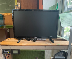
The pedal powered TV itself is a stationary recumbent bike that is connected to a generator to convert mechanical energy to electricity. It was first built and created in 1998 for the Campus Center for Appropriate Technology (CCAT) and redesigned in 2010. In the latest state of the pedal powered TV system, the TV was no longer being powered by pedaling no matter how hard one pedaled, indicating an electrical issue. CCAT Pedal Powered TV 2024 is a project with the objective to redesign and improve the 2010 version.
Team Mechanicals is a group of Mechanical Engineering students enrolled in ENGR 205, Introduction to design, for the Spring semester of 2024. Team Mechanicals is composed of the members Elise Evans, Jimena Gamero, August Scrivner, and James Pendergast VI.
Team Mechanicals is partnering with Campus Center for Appropriate Technology (CCAT), a student-run sustainability organization in Cal Poly Humboldt that experiments with and develops appropriate technology. Currently they have a pedal powered TV machine, located on the first floor of the CCAT building, that no longer works due to electrical issues. Additionally, CCAT needs a simpler pedal powered TV system and presentational instruction post with diagrams to teach people the mechanics behind the machine and the benefits of pedal power.
The objective of this project is to redesign and improve the original electrical components of the pedal power TV and produce a fully functioning recumbent bike station that powers a TV.
Team Mechanicals considered eight main criteria for their design. The criteria is used to guide design based decisions. For example, aesthetics was thought about in organizing cables and attaching different displays.
Criteria
Constraint
Weight (1-10 high)
Embedded Energy
70% or more of materials are reused.
7
System Efficiency
Takes less than 30 seconds for the TV to power up as soon as the user starts pedaling.
7
Aesthetics
Better looking and better organized than its predecessor.
5
Ease and Adaptability of Use
Doesn’t take an average college student more than 3 minutes to figure out how to use it and can be used more than one way.
8
Cost
Total cost is less than or equal to $500.
10
Reliability
Lasts at least 4 years before it needs major repair.
7
Repairability
More than 70% of the time an average college student can repair it themselves.
9
Educational Value
More than 50% of users say they learned something about renewable energy after using it.
The team undertook multiple prototyping designs. One major design was a cardboard model of the table and front of the bike. This prototype was constructed out of cardboard, hot glue, tape, and markers. This prototype helped with understanding scale as well as cable management. The tape used to represent wires is guided along the walls of the box. This helped estimate how much wire will be needed and if the wires will fit in the desired orientation. The wires also gave the team an idea of where to place cable fasteners. The components are placed on the left-hand side of the box and were able to fit in the team's protype indicating that space would not be an issue. The tv helped understand scale because from the prototype a rough idea of the tv’s size in comparison to the table could be easily observed. This prototype helped the team learn about compatibility and aesthetics.
Another important prototype was the poster prototype. This prototype was created digitally. The goal of this prototype was to find a logical numbering system in which the participants could easily follow. In addition to this poster is an informational list of the different components functions as they relate to transporting energy. This poster prototype helped the team learn about organization in terms of education.
The recumbent bike seat, pedals, wheel, belt, and table system from the original design was kept the same. The generator and cigarette port receptacle were also kept the same. These elements did not need to be updated as they were working completely fine and did not affect the efficiency required for the final product. The new parts that were implemented in the final design are detailed below:
Ketotek digital meter:
Includes voltage, current, power, and energy measurement readings
Is connected directly to the generator, therefore all readings are direct outputs from pedal power
Easy to read
The DC/DC Buck Boost Converter
Drok DC buck boost converter
Takes in fluctuating voltage between 5-30V and outputs a stable voltage, anywhere between 0-30V
In this design, it is set to output a stable constant 12V to power the TV
Includes inbuilt low voltage, over voltage, over current, over power, and over temperature protections.
Supersonic 19-Inch LED HDTV
Supports DC power
Supports streaming
1080p picture quality
Includes a built-in DVD player
Takes 36W to power (12W lower than the original)
The new 19 inch TV6 inches bigger than original
BMK 200W AC Inverter
Takes in DC and outputs AC
Includes 1.2A & 2.4A USB, 1 QC3.0 USB, 1 type C port, and 2 AC outlet ports
Can power/charge common devices like phones or laptops
Additionally, in the final design it was imperative that the wires and cables were replaced and reorganized from the original state to improve the simplicity and fixability. This way, CCAT employees can easily diagnose problems and understand the proper placement of wires.
See CCAT's 2010 Pedal Powered TV construction page for construction instructions of the recumbent bike and table setup as this was not changed in our 2024 redesign of only the electrical components.
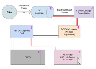
For the electrical component's the construction process was as follows:
Pedal Powered TV 2024 Circuit DesignConnect red and black wires to the generator (2) output
Use wire staples to keep long wire in place against the wooden cage
Connect wires from generator to digital meter (3) input
Inputs are labeled "+ in" (for red wire input) and "- in" (for black wire input)
Use flathead screw driver to loosen or tighten inputs
Connect new red and black wires to digital meter (3) output
Outputs are labeled "+ out" (for red wire output) and "- out" (for black wire output)
Use flathead screw driver to loosen or tighten outputs
Use velcro strips to stick digital meter into desired place against wooden table
Connect wires from digital meter output to DC buck boost converter (4) inputs
Inputs are labeled "+ in" (for red wire input) and "- in" (for black wire input)
Use flathead screw driver to loosen or tighten inputs
Connect new red and black wires to buck boost converter outputs
Outputs are labeled "+ out" (for red wire output) and "- out" (for black wire output)
Use flathead screw driver to loosen or tighten outputs
Start pedaling bike to turn on the buck boost converter and use the knob to change the constant voltage setting to 12V
Refer to Drok DC Converter Manual for settings adjustments
Use velcro strips to stick buck boost converter into desired place against wooden table
Connect wires from buck boost converter outputs to DC cigarette port receptacle (5) inputs
Attach DC cigarette port receptacle against wooden frame using a drill and screws
Insert DC TV cigarette plug into DC cigarette port receptacle
Once everything is attached and well secure, test that the digital displays (of the meter and buck boost converter) and TV power light (blue) lights up by pedaling at a 10-15V range
The Pedal Powered TV should be dusted regularly with a soft duster to prevent anything from diminishing the quality of the electrical components. General inspections of all components will be necessary to ensure the Pedal Powered TV’s function. General inspections of the wires, belt, various bolts and flywheel should be performed weekly. Dustings should be performed monthly. If there seems to be too much resistance, lubricate the chain on the inside of the pedal powered TV with dry chain lube.
The Pedal Powered TV is now functional and the effort of pedaling required to keep the TV on has decreased. The DC/DC converter required to power the DC TV functions perfectly, but the AC inverter is unable to power large devices and the system cannot power the inverter and the TV at the same time.
Previously, the Pedal Powered TV did not turn on because of a faulty voltage stabilizer. We tested the voltage coming out of different locations along the circuit and came top the conclusion that the voltage stabilizer was the issue. We decided to replace that with a DC/DC converter that would stabilize the voltage for a DC TV and replace the AC TV with a DC one.
After getting the old AC TV working and then replacing it with the new DC TV we compared the effort required to keep the TVs on and found that it was much easier to pedal, making the overall experience much more enjoyable.
When discussing what we wanted on our project, our team decided we wanted a place to charge cellphones and laptops. After receiving the inverter, we did lots of testing trying to get it to work at the same time as the TV. However, after testing, we discovered that the current being generated by the bike was not enough to supply the TV and charging a device at the same time. We also attempted to charge a laptop through the inverter, but were unsuccessful.
Our team gained a lot of knowledge on electricity during this project including topics like voltage, current, power, energy, circuitry, DC vs AC power, and more.
Some things we would do differently next time is start testing the electrical components and circuitry earlier in the process. This would’ve allowed more time towards the end to think about additional ways to make the system more efficient, like improving the power output from the generator by messing with the gear ratios. Another thing we would do differently is prepare the tools we would need for the project, like multimeters, screwdrivers, hammers, and wire cutters/strippers. Most of the construction process in this project was done with a mini multitool, which came with its obstacles and limitations.
Some future design improvement that can be made for this project is increasing the power output from the generator. An idea we had for this is to increase the gear ratio. Another improvement that could be worked on is the AC inverter. Currently the AC inverter and TV can’t be powered at the same time. The AC outlets also don’t seem to function properly and pedal power can’t seem to power a laptop through the AC inverter.
Make sure all plugs and wires are secure and not frayed. Replace any damaged parts.
Gauges not staying put
Replace adhesive Velcro strips.
Wires are cut/frayed
Cut the wire, strip the end and add in a short section of replacement wire.
Belt is worn out/broken
Find the type of belt, written in white text on the belt's surface and order a new one. The input wheel will need to be removed with a basic socket set before removal and put back on after putting on the new belt.