(One intermediate revision by the same user not shown)
Line 1:
Line 1:
{{MOST}}
{{MOST}}
{{MOST-RepRap}}
{{MOST-RepRap}}
{|
=Materials and Tools=
{| style="margin:auto;"
|-style="vertical-align:top;"
|[[File:MOST_base_mount_material.JPG|thumb|400px|alt=Base plate mounting materials|Base plate mounting material - both end assemblies and plywood rounds.]]
{|class="wikitable" style="margin:auto"
|+Materials
!Description
!Count
|-
|-
|[[File:MOST_base_mount_material.JPG|thumb|400px|alt=Base plate mounting materials|Base plate mounting material - both end assemblies and plywood rounds.]]
|34cm diameter plywood rounds
||[[File:MOST_base_mount_tools.JPG|thumb|400px|alt=Necessary tools|Necessary tools for mounting base plates.]]
|2
||{{template:MOST Delta Nav}}
|-
|M3 threaded rod, 85mm long
|12
|-
|#6 x 3/4" sheet metal screw
|24
|-
|M3 flat washer
|24
|-
|M3 nut
|24
|}
|
|[[File:MOST_base_mount_tools.JPG|thumb|400px|alt=Necessary tools|Necessary tools for mounting base plates.]]
{|class="wikitable" style="margin:auto"
|+Tools
|-
|Drill motor
|-
|8mm drill bit
|-
|Screwdriver
|-
|Optional - 2mm drill bit
|-
|-
|Optional - sharp pencil
|}
|}
|}
=Marking and drilling pilot holes (OPTIONAL)=
=Note=
=Procedure=
==Marking and drilling pilot holes (OPTIONAL)==
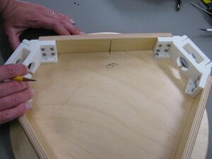
# [[File:MOST_Delta_025.JPG|thumb|right|Positioning base plate under motor end assembly, marked "B" for bottom.]]Lay the motor or idler end assembly on top of one of the round pieces of plywood with the flanges down and carefully position it such that the assembly is centered on the circle. Mark the locations of the base plate mounting screws with a sharp pencil or other sharp object taking care to not move the two pieces relative to each other. (Clamping or starting a pair of screws can keep the two pieces from moving relative to each other.)
# [[File:MOST_Delta_025.JPG|thumb|right|Positioning base plate under motor end assembly, marked "B" for bottom.]]Lay the motor or idler end assembly on top of one of the round pieces of plywood with the flanges down and carefully position it such that the assembly is centered on the circle. Mark the locations of the base plate mounting screws with a sharp pencil or other sharp object taking care to not move the two pieces relative to each other. (Clamping or starting a pair of screws can keep the two pieces from moving relative to each other.)
# Mark the relative location of the motor end assembly to the base plate by drawing a line through the center of one of the linking boards and a matching line on the round plywood piece. Mark the round plywood piece to indicate whether it is for the idler or motor end.{{clear}}
# Mark the relative location of the motor end assembly to the base plate by drawing a line through the center of one of the linking boards and a matching line on the round plywood piece. Mark the round plywood piece to indicate whether it is for the idler or motor end.{{clear}}
# Drill 2mm (1/16") pilot holes in the locations marked, but do not drill through the board.
# Drill 2mm (1/16") pilot holes in the locations marked, but do not drill through the board.
=Attaching Base Plates=
==Mounting bases==
# Center the motor or idler end assembly over a plywood round. If there are pilot holes, line up the assembly with marks made during marking of pilot holes.
# Center the motor or idler end assembly over a plywood round. If there are pilot holes, line up the assembly with marks made during marking of pilot holes.
# [[File:MOST_Delta_screwing_on_base_plate.JPG|thumb|right|Attaching base plate to end assembly with #6 x 3/4" sheet metal screws.]]Attach the motor or idler end assembly to the plywood round with #6 x 3/4" sheet metal screws. After tightening the first screw, check again that the assembly is centered on the round and start the second screw in one of the other vertices.{{clear}}
# [[File:MOST_Delta_screwing_on_base_plate.JPG|thumb|right|Attaching base plate to end assembly with #6 x 3/4" sheet metal screws.]]Attach the motor or idler end assembly to the plywood round with #6 x 3/4" sheet metal screws. After tightening the first screw, check again that the assembly is centered on the round and start the second screw in one of the other vertices.{{clear}}
# Attach base plates to both ends (motor and idler).
# Attach base plates to both ends (motor and idler).
=Inserting Clamp Threaded Rods=
# Check that an M3 nut will thread onto the M3 x 85mm threaded rods from both ends. Check each threaded rod before proceeding.
# Check that an M3 nut will thread onto the M3 x 85mm threaded rods from both ends. Check each threaded rod before proceeding.
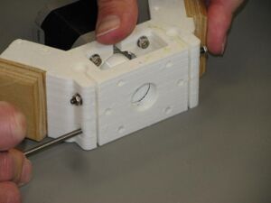
# [[File:MOST_Delta_030.JPG|thumb|right|Motor end with guide rod clamping screws.]]Place an M3 washer and nut onto one of the 85mm long M3 threaded rods. With the motor end assembly flat on the table, push the threaded rod through one of the motor end guide rod clamps. Place an M3 washer and nut on the opposite end of the threaded rod. Do not tighten the nuts. Repeat with the remaining clamp and proceed to the next remaining motor ends doing likewise.{{clear}}
# [[File:MOST_Delta_030.JPG|thumb|right|Motor end with guide rod clamping screws.]]Place an M3 washer and nut onto one of the 85mm long M3 threaded rods. With the motor end assembly flat on the table, push the threaded rod through one of the motor end guide rod clamps. Place an M3 washer and nut on the opposite end of the threaded rod. Do not tighten the nuts. Repeat with the remaining clamp and proceed to the next remaining motor ends doing likewise.{{clear}}
# Repeat with the idler end assembly.
# Repeat with the idler end assembly.
=Drill Wire Passages=
# Holes need to be drilled in one of the linking boards in each end for wires to pass through. The holes should be located near one of the printed ends.
# Holes need to be drilled in one of the linking boards in each end for wires to pass through. The holes should be located near one of the printed ends.
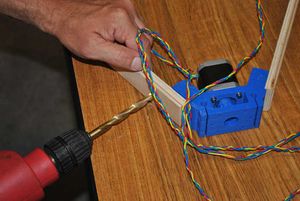
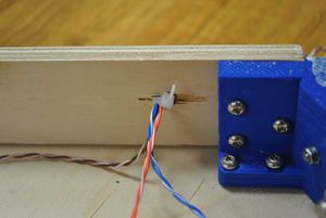
# [[File:MOST_Delta_motor_end_wire_hole.JPG|thumb|right|Drilling wire passage in motor end.]]Drill an 8mm (5/16")hole through one of the linking boards on the motor end assembly near one of the printed motor ends. Ream the hole well with the drill bit.{{clear}}
# [[File:MOST_Delta_motor_end_wire_hole.JPG|thumb|right|Drilling wire passage in motor end.]]Drill an 8mm (5/16")hole through one of the linking boards on the motor end assembly near one of the printed motor ends. Ream the hole well with the drill bit.{{clear}}
Line 33:
Line 65:
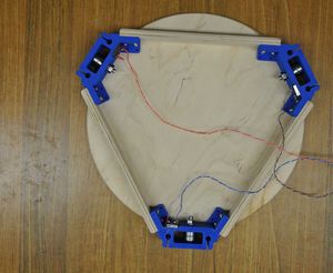
[[File:MOST_Delta_completed_end_assembly.JPG|400|center|Completed end with base plate.]]
[[File:MOST_Delta_completed_end_assembly.JPG|400|center|Completed end with base plate.]]
Base plate mounting material - both end assemblies and plywood rounds.
Materials
Description
Count
34cm diameter plywood rounds
2
M3 threaded rod, 85mm long
12
#6 x 3/4" sheet metal screw
24
M3 flat washer
24
M3 nut
24
Necessary tools for mounting base plates.
Tools
Drill motor
8mm drill bit
Screwdriver
Optional - 2mm drill bit
Optional - sharp pencil
Note
Procedure
Marking and drilling pilot holes (OPTIONAL)
Positioning base plate under motor end assembly, marked "B" for bottom.Lay the motor or idler end assembly on top of one of the round pieces of plywood with the flanges down and carefully position it such that the assembly is centered on the circle. Mark the locations of the base plate mounting screws with a sharp pencil or other sharp object taking care to not move the two pieces relative to each other. (Clamping or starting a pair of screws can keep the two pieces from moving relative to each other.)
Mark the relative location of the motor end assembly to the base plate by drawing a line through the center of one of the linking boards and a matching line on the round plywood piece. Mark the round plywood piece to indicate whether it is for the idler or motor end.
Drill 2mm (1/16") pilot holes in the locations marked, but do not drill through the board.
Mounting bases
Center the motor or idler end assembly over a plywood round. If there are pilot holes, line up the assembly with marks made during marking of pilot holes.
Attaching base plate to end assembly with #6 x 3/4" sheet metal screws.Attach the motor or idler end assembly to the plywood round with #6 x 3/4" sheet metal screws. After tightening the first screw, check again that the assembly is centered on the round and start the second screw in one of the other vertices.
Attach base plates to both ends (motor and idler).
Check that an M3 nut will thread onto the M3 x 85mm threaded rods from both ends. Check each threaded rod before proceeding.
Motor end with guide rod clamping screws.Place an M3 washer and nut onto one of the 85mm long M3 threaded rods. With the motor end assembly flat on the table, push the threaded rod through one of the motor end guide rod clamps. Place an M3 washer and nut on the opposite end of the threaded rod. Do not tighten the nuts. Repeat with the remaining clamp and proceed to the next remaining motor ends doing likewise.
Repeat with the idler end assembly.
Holes need to be drilled in one of the linking boards in each end for wires to pass through. The holes should be located near one of the printed ends.
Drilling wire passage in motor end.Drill an 8mm (5/16")hole through one of the linking boards on the motor end assembly near one of the printed motor ends. Ream the hole well with the drill bit.
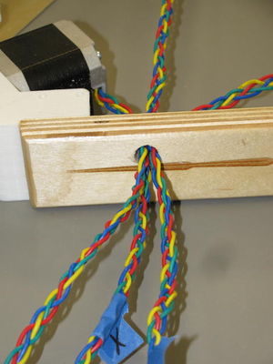
Motor leads passing through 8mm hole in linking board.Carefully feed the braided motor wires through the hole in the motor end linking board.
As with the motor end, drill an 8mm (5/16")hole through one of the linking boards on the motor end assembly near one of the printed idler ends.
Carefully feed the limit switch wires through the hole in the idler end linking board.
Bundle limit switch wires together.To provide strain relief for the limit switch wires, bundle them together with a small wire tie on the inside of the idler end assembly.