| Line 3: | Line 3: | ||
== '''Background''' == | == '''Background''' == | ||
Locally Delicious is a group of women collaborating on a new book titled "Lunch Box Envy." Several different Engineering 215 projects are to be included. The School solar dehydrator is one of them. | [[Locally Delicious]] is a group of women collaborating on a new book titled "Lunch Box Envy." Several different Engineering 215 projects are to be included. The School solar dehydrator is one of them. | ||
Team Member Pages: | Team Member Pages: | ||
Revision as of 23:25, 5 April 2011
Abstract
Background
Locally Delicious is a group of women collaborating on a new book titled "Lunch Box Envy." Several different Engineering 215 projects are to be included. The School solar dehydrator is one of them.
Team Member Pages: Alisha Sughroue Mary Wooldridge Justin Thompson James Courtney
Objective and Criteria
Objective
The objective of this project is to make the youth that participate in this project knowledgeable about food dehydration, conservation techniques, and food sustainability.
Critera
Several criteria were weighted and defined shown in the table below.
| Criteria | Weight | Description |
|---|---|---|
| Safety | 10 | This is defined as a structure being stable enough for children, having safe building materials for food quality, and having a completely finished project to protect children against loose material or sharp edges. |
| Cost | 9 | Design must cost less than $300. |
| Reproducible | 9 | This is defined as the ease of following the directions and constructing the solar dehydrator. |
| Durability | 8 | This is defined as having a structure that is able to last two to three years with regular use by adults and children. |
| Weather Resistance | 8 | This is defined as the structure’s ability to hold up against all types of weather. |
| Ease of Use | 7 | This is defined as a structure that has a design that is easily operated on a child’s level. |
| Efficiency | 7 | This is defined as the project's ability to dry food quickly and to dry the food to the operator’s expectations of good quality dehydration. |
| Aesthetics | 4 | This is defined as the project with a presentable and school appropriate design. |
Description of Final Project
This project was to design a solar food dehydrator to be replicated by schools.
Sunlight enters the slanted solar collector through the glazing, a polycarbonate sheet, and heats up a metal sheet. The air between the glazing and the solar collector warms, which causes it to become less dense and rise. As this air rises, it is replaced by outside air entering from the bottom of the collector which is then heated as well. The rising air eventually exits the collector and enters an insulated elevated cabinet with an air vent on the top. Since the air inside the cabinet is less dense than the outside air from being heated, it moves vertically within the cabinet and exits the cabinet through the vent. The cabinet contains horizontally oriented frames with nylon mesh in which produce is placed on. This produce dries from the moving hot air it is exposed to.
The solar collector contains a black painted copper sheet which sits on top of insulation within a polycarbonate covered wood box.
Costs
| Materials | Use | Quantity | Project Cost ($) | Projected Cost ($) |
|---|---|---|---|---|
| Small Cabinet | Dryer Box | 1 | 6.00 | 40.00 |
| Screen | Covering End of Solar Collector | 1 | 1.00 | 4.00 |
| Styrofoam Insulation | Insulation of Solar Collector | 4 | 1.50 | 60.00 |
| Copper Sheet Metal | Heat Conductor for Solar Collector | 63" X 27" | 40.00 | 40.00 |
| Metal Roof | Roofing for Weather Protection | .97 tons | 5.00 | 12.00 |
| Insulation | Insulation for Dryer Box | 5'X 4' | 22.82 | 22.82 |
| Polycarbonate and Fitting Screws | Glazing Material | 10' X 26" | 45.89 | 45.89 |
| Screws, Sealant,Latch, and Polyfoam | Putting together Solar Collector Glazing | N/A | 30.91 | 30.91 |
| Tacks | Securing Insulation | 1 box | 1.34 | 1.34 |
| Caulking | Not used | 1 tube | 5.84 | 0.00 |
| Hinges | For Cabinet Doors(not used) | 2 packs | 9.88 | 0.00 |
| Hinges and Piping | Cabinet Doors and Connecting Solar Collector | N/A | 9.27 | 9.27 |
| Nylon Mesh | Drying Racks | 3 yards | 6.08 | 6.08 |
| All Lumber | Collector Box, Drying Racks, and Base | N/A | 0.00 | 33.00 |
| Polyvert Closure | Set Glazing on top of | 6 | 5.99 | 5.99 |
| Paint | Whole project | 1 can | 31.00 | 31.00 |
| Total | 222.52 | 265.31 |
Testing Results
How to Build
Drying Cabinet
The drying cabinet, shown in Figure 3, the Sodhoppers used was actually a recycled cupboard. Any sort of box would have been a good candidate for the body of the dryer. The doors were removed and insulation was stapled to the inside of the cabinet,shown in Figure 3a. Next the shelving was put in. It consisted of 4 blocks of wood standing at each corner and smaller pieces of wood branching off them to form a shelf that the drying racks could easily sit on. The Drying box with racks inside is shown in Figure 3h. Then the doors were put back on with new hinges and a latch to secure the doors.
Solar Collector
The Solar Collector, shown in Figure(not yet added) is built using plywood and two by fours. The frame is shown in Figure 3b. The wood is fit together to create a rectangular box of 65” X 27”, with plywood acting as a base. Then the box is insulated by fitting pieces of recycled Styrofoam together on the base, shown in Figure 3d. Next the copper metal sheet, acting as a heat conductor, is placed on top of the insulation. Lastly, the corrugated polycarbonate panel, acting as a glazing, is fit on top of the box using special corrugated end pieces and side pieces, and finally screwed down.
Drying Racks
The Drying Racks are constructed from strips of plywood and nylon mesh, shown in Figure 3e. The mesh was placed in between a plywood base and top. It was stapled to the base and then the top was screwed down effectively holding the mesh down to create an air-movement-friendly drying rack. The finished product is seen in Figure 3f.
Base
The Base, shown in Figure 3g, was constructed from four 4 X4’s, plywood, and plexiglass. The plywood was set on top of the 4X4’s and the plexiglass was mounted on each side to prevent the drying cabinet from moving.
-
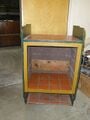
Fig 3: Cabinet before work starts.
-
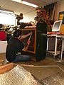
Fig 3a: Justin Thompson measuring for insulation.
-
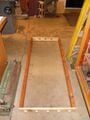
Fig 3b: Frame of Solar Collector.
-
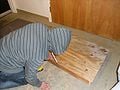
Fig 3c: Justing Thompson attaching base to Solar Collector.
-
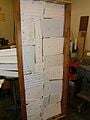
Fig 3d: Insulated Solar Collector.
-
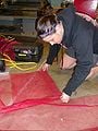
Fig 3e: Mary Wooldridge cutting nylon mesh for drying racks.
-
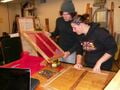
Fig 3f: James Courtney and Mary Wooldridge inspecting a finished drying rack.
-
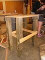
Fig 3g: Finished base.
-
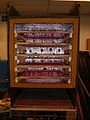
Fig 3h: Finished Dryer Box.
-
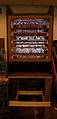
Fig 3i: Finished Dryer Box including Base.


