
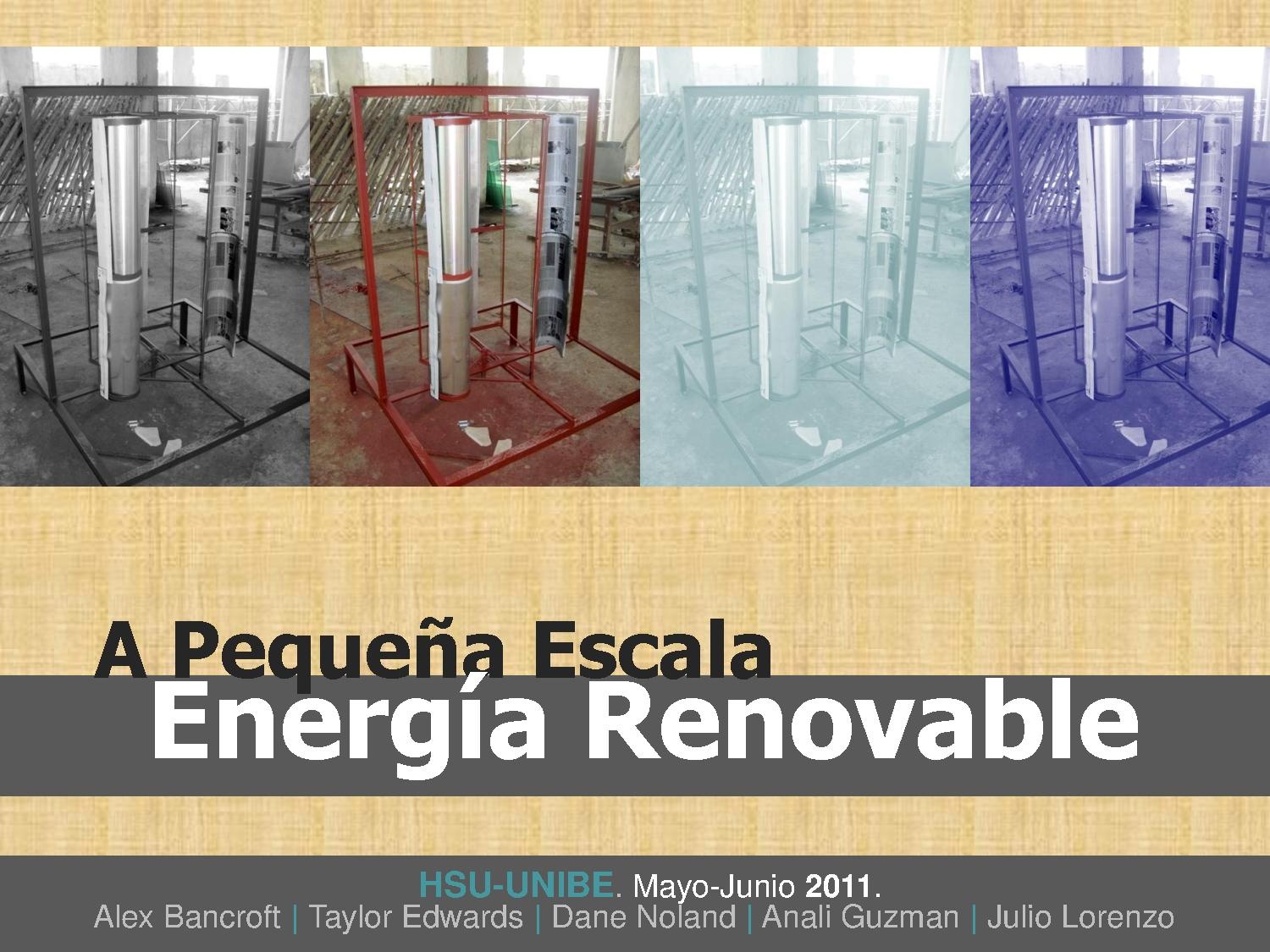
Objective Statement
The objective of this Appropriate Technology project was to construct a small scale renewable energy system. This system was designed to serve as an educational tool, reduce fossil fuel use, along with having an acceptable pay-back time.
Background
In the Summer of 2011 the Humboldt State University Dominicana Program worked in collaboration with Universidad Iberoamericana (UNIBE), REVart, and the community of La Yuca, Santo Domingo. Together, they worked on exploring solutions to the energy demands of La Yuca. It was chosen that a prototype solution would be designed and constructed. The finished product consists of two components, a small scale vertical axis wind turbine and a 10 watt solar panel.
Location
La Yuca del Naco, Santo Domingo, Dominican Republic

Criteria
Table 1: Criteria
| Criteria | Weight | Description |
|---|---|---|
| Safety | 10 | Safety is the ability of the design to prevent injury of any kind. The small scale renewable energy system must not be unsafe. |
| Effectiveness | 10 | The effectiveness of the small scale renewable energy system is the extent to which the system transfers energy, can be used as an educational tool, and the system's ability to be marketed locally. |
| Durability | 10 | Durability is the ability of the system to sustain a functioning state. |
| Aesthetics | 5 | Aesthetics is the system's level of visual appeal. |
| Payback Time | 8 | The small scale renewable energy system must have a payback time of one year or less while having an initial cost of USD $200. |
| Maintainability | 8 | Maintainability of the system is defined as the total cost required to sustain the functionality of the system. The maintenance cost is measured in money and in time. |
| Reproducibility | 8 | Reproducibility of the design is defined as the ability to which the design is able to be reproduced and marketed. |
The Design
During six weeks of intensive study and work, the group decided to utilize a solar-wind hybrid system. The reason for this decision is due to climate of La Yuca. It was noticed that the area did not receive a large amount of usable wind speeds. However, there was a large quantity of sunlight in the region. Moreover, the wind appeared to be the strongest when there was little to no sun. By combining the two systems we felt that we could better utilize the available natural resources.
The group decided to use our system to light the room that the appropriate building group built for the Escuela Basica Nurys Zarzuela in La Yuca.
-
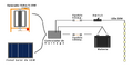
Figure 2a: A basic diagram showing the components of the system and how they are connected
-
Figure 2b: The LED's that were used to light the storage room
-
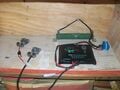
Figure 2c: This photo shows the box used to hold and protect the electrical components of our project. This box was fastened to the wall and the car battery was later added
-
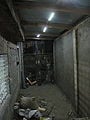
Figure 2d: The LED's being utilized to light the storage room at night


Turbine
Due to the variation in wind speeds as well as direction, a VAWT was determined to be the best suited turbine design. The diagrams in Figure 3 bellow give a more detailed look into the design of the turbine and the turbine frame.
-
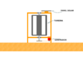
Figure 3a: The basic design of the turbine. The solar panel was attached to the top of the frame and the motor to the bottom of the frame. The motor was turned using gears and a chain attached to the turbine.
-

Figure 3b: This picture shows the blade design. This design was researched to utilize lift force which are often used low wind areas.


Design and Construction Process

Design
- Decided upon a solution by:
- Determining and weighing project criteria
- Discussing alternative solutions
- Determining and weighing project criteria
- Built several prototypes for testing, one can be seen in Fig. 4
- Used a scalable vector graphics program (SVG) to design the turbine's blades
Construction
- Built blade frames
- Fastened aluminum sheeting to the blade frames, aluminum donated by the local newspaper company
- Built the main frame that would house the blades, Figure 5b
- Attached the blades to the frame using bearings
- Mounted the permanent magnet and sprockets
- Connected the bike chain to between the motor and the shaft sprocket, Figure 5d
- Welded feet to the legs of the frame which were used to bolt the turbine to the cement roof
- Welded a flat metal piece to the top of the frame which would hold the solar panel
Materials used:
- Angle Iron
- Sheet metal
- Bicycle gears
- Bicycle chains
- Bearings
- Rebar
- Solid metal pipe
-
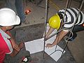
Figure 5a: Configuring the turbine blades with the printed design
-
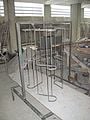
Figure 5b: The turbine main frame and turbine blade skeleton
-
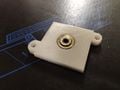
Figure 5c: One of the bearings used to connect the blades to the main frame
-
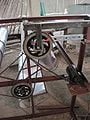
Figure 5d: Gearing connected by bicycle chains


Electronics
Electrical energy is transferred from both a 10W solar panel and a wind turbine capable of achieving 30W at full capacity. By using a hybrid solar-wind power system, the battery bank is able to charge during the day by solar power and charged by wind power when there is ample wind. When storms approach, the wind generator will be able to produce power since insolation is minimal during full cloud cover. This hybrid system is meant to increase the overall time in which the batteries are charging.
Electricity is sent from the tandem power sources across a 14 gauge electrical wire to a charging station. This wire should be a short distance in order to reduce electrical loss from the transmission of electrons over long distances. If there is a need to transmit power over a large distance (<100ft) a transformer may be necessary to raise the voltage level to an appropriate level as to not incur as much voltage loss (110-220V). This electrical power is sent to a 24V relay which is able to divert the electricity away from the batteries in the case of a voltage spike from high wind gusts. This diversion of power is sent to a shunt resistor. The shunt resistor is a coil of wire which will convert electrical energy into thermal energy, producing a greater load on the wind turbine. This slows the turbine down until it reaches a lower speed and will not overcharge the system.
If the system is not overcharging, the electrical energy it transmitted from the relay to a solar charging controller. This controller has multiple functions and will take on the job of regulating battery charging voltage, switching on/off a 12/24V circuit through a timer or if system voltage is too low, and will display the status of the charging system, batteries and 12/24V circuit. The model used in this system was a pulse width modulated EPRC-5. The charge controller has three pairs of terminals for electrical connections: solar panel-wind generator, batteries and lighting. Attached to the controller is a display for functions such as: automatic lighting control, timers, test mode and controller mode. In the current system, the controller was programmed to “Mode-6” which ran the controller without any automatic lighting control or timers.
The battery bank was connected directly to the EPRC-5 charge controller with the sole addition of an inline fuse rated at 8amps. The charge controller is able to regulate battery voltage and maintain a full charge when there is ample power to supply. The lighting used was a series of 12V LEDs, and thus were also directly connected to the lighting terminals of the charge controller adjoined to a 4amp fuse and switch. The LEDs where wire to the ceiling of a room and were turned on and off with the flip of the nearby switch.
The charging station was constructed into a box mounted to the wall and easily accessible with a hinged cover and pad lock. The box was inside of the room in order to prevent water and weather from harming the system electronics.
If there are any questions about the construction or troubleshooting of the system, please contact Alex Bancroft at his university e-mail: ab290@humboldt.edu
Components
| Device | Specifications | Description | Picture |
|---|---|---|---|
| The Solar Panel | 10 watt | This panel was used in parallel with the turbine to transfer solar radiation into electrical energy. |  |
| Shunt | GH-120W 50Ω | A shunt is a device that acts as a bypass, which allows current to pass through another point in the circuit. For this project, the shunt was used to dissipate excess energy in the form of heat. |  |
| Solar Charge Controller | 12/24V
5A |
The solar charge controller regulates the voltage that goes from the solar panels to the battery. Most solar charge controllers monitor the battery charge and will open the circuit when the battery is full, thereby stopping the charging process. |  |
| LED | 27 LEDs
33.75W (for the entire light series) |
Light Emitting Diodes that were used for our project due to their high light output at low wattage. |  |
| Car Battery | 12V
40Ahr |
The charge on the battery will be used to light the LEDs in the system. |  |
| Permanent Magnet Motor | 90V DC, 1.4A, 1745rmp (max)
0.10hp |
The permanent magnet motor is used to convert the mechanical energy of the turbine movement to electrical energy. |  |
| Relay | 24V | The relay is used to divert unwanted, or excess, current to the shunt. |  |
Cost
Budget
| Materials | Unit Price (DOP) | Quantity | Cost (DOP) | Cost (USD) | Our Actual Cost (DOP) | Our Actual Cost (USD) |
|---|---|---|---|---|---|---|
| 10 watt Solar Panel | 2,850 (1,710 donated) | 1 | 2,812 | 75 (45 donated) | 1,125 | 30 |
| Gears | 410 | 1 | 410 | 10.93 | 410 | 10.93 |
| Permanent Magnet Motor and Shunt | 1,500 | 1 | 1,500 | 40.00 | 1,500 | 40.00 |
| Battery and Terminals | 1,870 | 1 | 1,870 | 49.86 | 1,870 | 49.86 |
| Diodes, Switches, and Zeners | 50 | 1 | 50 | 1.33 | 50 | 1.33 |
| Inverter | 1,400 | 1 | 1,400 | 37.33 | 1,400 | 37.33 |
| Solar Charge Controller | 1,300 | 1 | 1,300 | 34.67 | 1,300 | 34.67 |
| LED lights | 55.50 (donated) | 27 LEDs | 1,498.50 | 39.96 | free | free |
| Electrical wire | $5/ft | 300ft | 1,500 | 40 | 1,500 | 40 |
| Turbine (construction labor) | $20,000 (donated) | 1 | 20,000 | 533.33 | free | free |
| Black Metal Pipe | 635 | 1 | 635 | 16.93 | 635 | 16.93 |
| Angular Iron | 2,435.47 | 1 | 2,435.47 | 64.95 | 2,435.47 | 64.95 |
| Total = | $35,411.47 | $944.31 | $12,225.47 | $326.01 |
Timeline

Results
Payback Time


The payback time of the system has been divided into two parts. The payback time has been calculated separately for the wind turbine and the solar panel.
Wind Turbine
The payback time for the wind turbine was calculated using an estimated energy output or energy savings of or . Also, the payback period was calculated excluding any labor costs as these services were donated. The cost of energy used to calculate the payback period was [1].


As seen in Figure 7, the payback period of the wind turbine is approximately 59.63 years. The equations used to calculate the wind turbine payback period are shown here:


Solar Panel
As seen in Figure 8, the payback period of the solar panel was calculated to be 14.9 years. A 22 year average of 5.07 hours of full sun per day was used in the calculations[2]. Also, the cost of energy used to calculate the panel's payback period was . The equations used to calculate the solar panel payback period are shown here:


Authors and Team Members
Taylor Edwards
Rosa Anali Guzman Molina
Dane Noland
Alex Bancroft
Julio Lorenzo

Helpful Files
 Power Point Presentation on PDF
References
- ↑ "Electricity Prices for Households." Energy Information Administration, 10 June 2010. Web. 9 Sept. 2011. <http://www.eia.gov/emeu/international/elecprih.html>.
- ↑ "Parameters for Sizing and Pointing of Solar Panels and for Solar Thermal Applications - Pivot Data - Santo Domingo, Dominican Republic." Метеостатистика для Доминиканской Республики. Meteostatistics for the Dominican Republic. Web. 9 Sept. 2011. <http://dominican-meteo.ru/en/santo-domingo/pivot/solar-panels>.