Background
Parras de la Fuente
Parras de la Fuente is a desert oasis town of about 44,000 residents located in the south of the Mexican state of Coahuila. Along with textile manufacturing, tourism is one of the main industries in Parras. Tourism has become increasingly emphasized after Parras's designation as the "primer pueblo mágico del Norte de México." Parras is warm in the summer, and cooler in the winter, but temperatures rarely fall below freezing, snow falls once every several years.
- Elevation
- 1,505 m
- Longitude
- 102°11'W
- Latitude
- 25o30’ N
Hotel Perote
Antiqua Hacienda de Perote is a hotel, restaurant, nuez (pecan) ranch, vineyard, and winery. It sits on about 500 acres on the western-most edge of Parras. According to Igancio (Nacho) Chacon, Perote's owner, Perote's hotel business has been growing rapidly, and in 2006, the hotel was constructing rooms to meet demand.
Contacting Hotel Perote
- Visit Hotel Perote's in-town office, near UTC Parras
- Ramos Arizpe # 131 Col. Centro C.P. 27980
- Parras de la Fuente, Coahuila
- Call the Hotel Perote in-town office (see Phone Calls section of Parras Handbook)
- (842) 422 1698
- Fax
- (842) 422 0698
- Call Lic. Ignacio Chacon's (owner's) mobile phone
- Email Aaron Antrim to get this phone number
- Website
- Antiqua Hacienda de Perote
Visiting Hotel Perote
Go a few kilometers west on Calle Madero, the street in front of UTC Parras, passing turns for Estanque de la Luz and La Illusion. Consult this map from the Hotel Perote website for additional directions. A cab to Perote from UTC will cost 50 pesos. See the Taxis section of the Parras Handbook for more information.
2005 History
Parras Program students Heather Kuoppamaki and Rowan Steele built a rooftop solar hot water system for Hotel Perote in the summer of 2005. Intended as prototype for a larger system to heat a spring-fed swimming pool (alberca), then being constructed, the system was sized to provide heated water for a single hotel bathroom. For more information on the 2005 system, Heather and Rowan's final document for their system. The 2005 system is no longer located at Perote, and has been moved to the residence of someone afiliated with the local city government. For more on the whereabouts of this system, contact Ignacio Chacon.
2006 Project Design

Required system performance
Igancio has requested a system to keep the pool at 28° centigrade from October to March. The design problem revolves on this performance parameter and several state variables.
Existing site, equipment, and state variables
Pool dimensions

- Pool surface area
- (Necessary for considering heat loss)
- (11.2 by 6.7 meters)+(1.82*pi) = 85 square meters
- Pool volume
- The total volume of the pool is approx 112 cubic meters, or 112,000 liters.
Installation site dimensions
- Roof dimensions
- 77 ft by 31 feet
- Roof height from deck
- 26 feet
Pump specifications
-
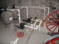
Figure 1: Currently, water is pumped through a sand filtration system.
-
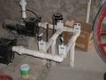
Figure 2: Close up of water flow valves.
-

Figure 3: Pump label. No additional flow rate information could be found from the information on this label.


The Solar Collector

|
The solar collector will be constructed of 30 three meter lengths of half inch diameter copper pipe run in parallel between two one and a half inch diameter PVC ends. The lengths of half inch copper pipe will be connected to the one and a half inch PVC pipe by PVC "T's". For easy testing, the system will include a spigot for obtaining water temperature readings at a point after the water has passed through the collector. A thermometer will also be installed in the pool to take temperature readings there. |
Connection to existing pool plumbing

The 2006 project team's design calls for the new rooftop solar collector to be connected to the pipe returning water to the pool after it has passed through the sand filter. Heating water after it has been filtered will prevent debris from clogging the solar hot water heating system. A gate valve can be closed to force water through the solar collector. When open, water will return directly from the filters to the pool without passing through the solar collector.
The pipes to the rooftop solar collector will share identical specifications with the existing pipes running to and from the pool: one and a half inch diameter "schedule 40" PVC. Schedule 40 PVC tubing is thicker than conventional PVC, and is used in pool systems. The additional thickness and strength of schedule 40 PVC will provide improved water pressure tolerance and improved heat and solar radiation tolerance, which will be important, as these PVC pipes will be carrying heated water, and will be exposed to heat and solar radiation on the roof.
The piping delivering and returning water from the rooftop system will first run directly up to the ceiling of the pump room from where it is connected to filter outflow. It will run along the ceiling to the point where it must pass through the concrete floor of the deck above to run [how many meters?] to the roof.
[calculate head loss for pipes running up to the roof]
Materials List
System design (duplicate to some info above, needs to be integrated with it)
The system will have a collector consisting of thirty runs of half inch copper pipe, each three meters in length. One and a half inch schedule forty PVC pipes will carry the water to and from the roof. The lengths of half inch copper pipe will be connected to the one and a half inch PVC pipe by tees. The collector will be connected after the filters and installed on the roof. Since the filters have pumps in them already, additional pumps will not be needed to carry the water up to the roof.
Performance estimations
Predicted temperature change in pool
T = (Vc/Fc)(Qp/mc)/(mtsw)
T = change in temperature Vc = volume of collector Fc = flow in collector Qp = heat transfer in pipe (from test) mc = mass of water which passes through collector mt = total mass of water sw = specific heat of water
Qp = mswT
Qp = heat transfer in pipe (from test) m = mass of water in pipe sw = specific heat of water T = change in temperature
Effectiveness of Solar Collector for Perote
The sizing of the collector for the pool system is difficult to determine. In order to maintain the pools temperature throughout the winter it is necessary to determine the energy loss of the pool during that time, something that is difficult to do in July. The system was designed based on the available supply of copper pipe, if this proves to be inadequate the system was constructed in such a way that it is easy to expand and therefore increase the detention time in the collector. At the first meeting at Hotel Perote 100 meters of half-inch copper pipe was made available for this project. This gives the collector a volume of 50.6 liters. The manual for the pumps was not available, and it was not possible to measure the flow before construction, so a estimate of 114 L/m was used for the flow rate. This flow rate was based on US pump sizing standards for the pool volume. Based on the collector volume and flow rate the hydraulic retention time is:
T = V/Q = (50.6 L)/(114 L/m) = 0.44 m
Unfortunately this retention time is rather small and the testes conducted with the copper pipe may not be accurate at this range. The water temperature in the test pipe gained about two degrees (C) per minute for the first couple of minutes in direct sun. Based on that data it was estimated than in the first half minute the temperature will increase one degree. The volume of water being heater was based on the flow rate and the equivalent of a minimum of 4.5 hours direct sun in the winter:
V = T*Q = (4.5 hr * 60 m / 1 hr) * (114 L/m) = 30780 L
To determine the energy added the volume is changed to mass using a density of 1 L/kg, which means that 30780 kg of water is heated 1C.
Q = mswT
Q = heat transfer m = mass of water sw = specific heat of water T = change in temperature
Q = (30780 kg)(4.186 kJ/kg* C)(1C) Q = 128845 kJ ≈ 129 MJ
The addition of 129 MJ per day seems large, however when considering the volume of the pool the effect may not be substantial. The only way to know weather the 129 MJ is enough is to monitor the pool temperature over the course of a year. If more heat needs to be added the collector volume can be increased without much difficulty.
External Links
"Water Heater Efficiency" [1]
"Energy From Natural Gas" [2]