
The Kenyan Low Cost Modular Timber Bridge
Note: The following report comes from the AT Sourcebook and is a government publication constituting open access.
Bibliographic Information
- ---
The Kenyan Low Cost Modular Timber Bridge. J.D. Parry, 1981.
PERFORMER: Transport and Road Research Lab., Crowthorne (England)
A novel design of a type of timber truss bridge has been developed in Kenya is described. The bridge comprises a number of identical timber frames that are assembled into trusses of the required span. Two or more parallel trusses are supported on conventional abutments, and the timber deck rests on top of the trusses. Loading tests carried out on individual frames, on groups of frames, and on complete bridges ranging in span from 12 m to 24 m required to carry limited numbers of vehicles up to 20 t gross weight provided that the deck is accepted as contributing to the structural strength of the bridge. This assumption would not normally be made for bridges of this kind, but in practice measurements show that the deck does contribute significantly to the strength of the bridge. (Crown copyright 1981.)
KEYWORDS: "Truss bridges", "Wooden bridges", "Foreign technology"
Available from the National Technical Information Service, Springfield, Va., U.S.A. 22161
PRICE CODE: PC A03/MF A01
Abstract
- ---
A novel design of a type of timber truss bridge that has been developed in Kenya is described. The bridge comprises a number of identical timber frames that are assembled into trusses of the required span. Two or more parallel trusses are supported on conventional abutments, and the timber deck rests on top of the trusses.
Loading tests carried out on individual frames, on groups of frames, and on complete bridges, have indicated that the design is suitable for bridges ranging in span from 12m to 24m required to carry limited numbers of vehicles up to 20 t gross weight provided that the deck is accepted as contributing to the structural strength of the bridge. This assumption would not normally be made for bridges of this kind, but in practice measurements show that the deck does contribute significantly to the strength of the bridge.
In lightly loaded situations, provided regular maintenance is undertaken, the bridge can be expected to have a life of 20 years. Evidence of the durability of the bridge at higher traffic loadings is not available. The cost of the bridge in Kenya is between one-half and one-fifth of comparable steel or concrete bridges.
Introduction
[edit | edit source]In 1973 a modular type of timber truss bridge was designed by Mr J E Collins of the Forest Department of the Ministry of Natural Resources in Kenya. He subsequently developed the design under a project sponsored by UNIDO (United Nations Industrial Development Organisation) and by early 1976 four bridges had been built in Kenya, and twelve more were planned.
The objective of the UNlDO project was to provide relatively cheap bridges to carry light commercial vehicles in rural areas. The design that was evolved fulfils that requirement but also has the additional advantage that the bridges can be erected quickly, and can be dismantled and re-erected at another site if required. As with the Bailey Bridge, the basic units can be stored in readiness for use in an emergency, and can be used to build bridges of various spans and load carrying capacities.
This report assesses the design, suggests some minor modifications to the design, reports the results of loading tests performed on single frames, groups of frames, and complete bridges, and provides guidance on safe loadings and costs.
General description
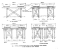
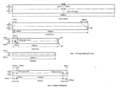
[edit | edit source]The bridge is a truss type, with the road deck carried on top of the trusses (see Plate 1). The upper chords of the trusses, the verticals, diagonals, bracings, and deck are all constructed from timber. The bottom chords and the joints are made from mild steel. Except for some minor modifications to the design suggested in Sections 52.3 and 7, all the details of the design, the dimensions, the methods of manufacture, and the quality control recommendations, were provided by the Forest Department of the Kenyan Ministry of Natural Resources. A set of drawings provided by the Forest Department is reproduced in Figures 1 to 10. The bridges built in Kenya were built to these drawings, using timber as specified in Section 3.1.1. The use of timber with different characteristics is not discussed in detail in this report, because the loading tests were made on frames built from the same grade of timber, and simple extrapolation of the results of dissimilar timbers is not possible.
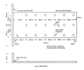
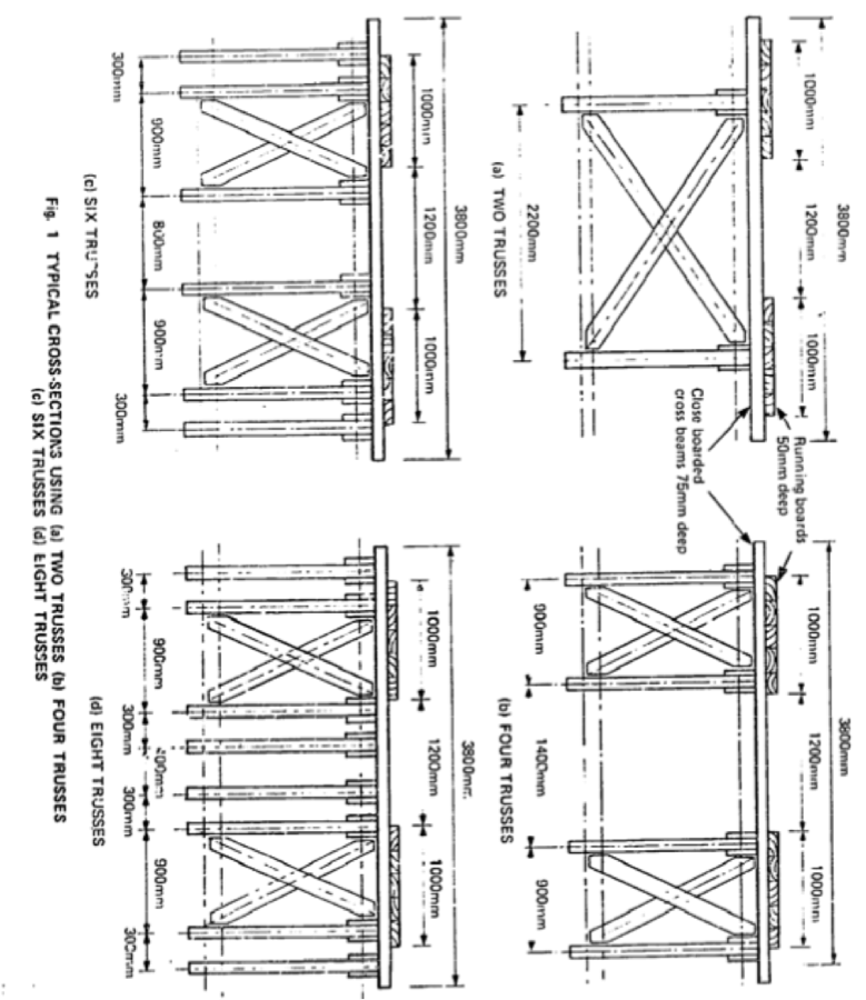
In a typical bridge, four trusses are positioned side-by-side, but the number of trusses can range from two to eight depending on the loading requirements (see Figure 1).
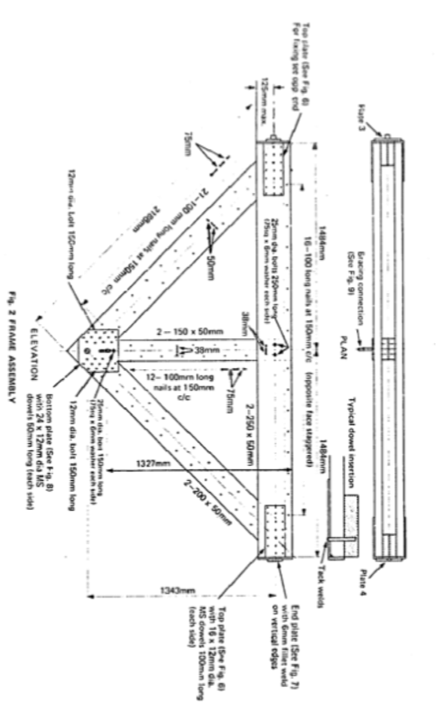
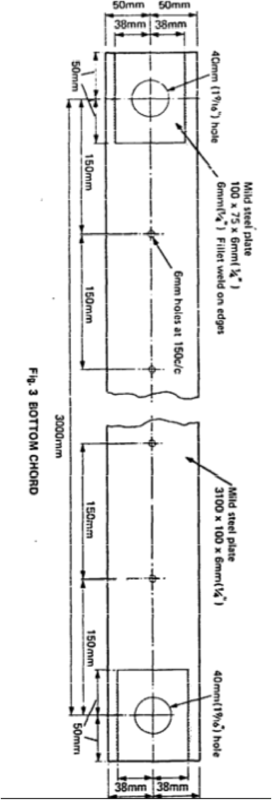
Each truss is assembled from a number of identical frames (Figure 2), prefabricated and transported to the site together with the steel bottom chords (Figure 3). The frames are made of rough sawn softwood boards 50 mm thick, dowelled and nailed together to form an inverted triangle 3 metres long with a vertical brace. They weigh about 140 kg each and are all made in the same manner. Practical considerations limit the number of frames in a truss from 3 or 4 to about 8 or 10, according to the properties of the timber employed.
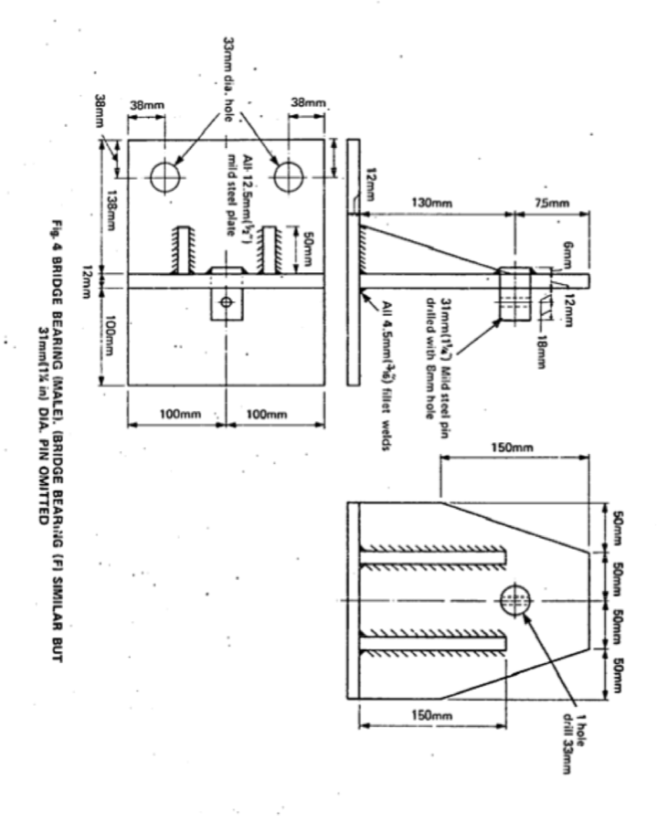
The trusses are connected by timber cross beams above, and diagonal bracing members, both vertical and horizontal, between the trusses. Longitudinal running boards are nailed to the cross beams (Figures 1 to 10). At their ends the trusses are supported by angle brackets (Figure 4), which act as the bridge bearings. Stone, concrete, brick or timber abutments may be used to support the brackets.
The main features of the design are:
- It utilizes local timber and, in Kenya's case, local steel as well.
- It is easy to fabricate using relatively simple tools.
- The largest component measures 3 metres by 1.5 metres and is light enough to be manhandled.
- All the frames are identical and so may be made on a jig in a workshop, where inspection of quality and finish is easier than on site.
- In Kenya the cost is much lower than that of a steel or concrete bridge with similar loading capacity.
The bridge components
[edit | edit source]The frames for the Kenyan bridges were constructed in a workshop of the Ministry or Natural Resources in Nairobi and were transported to site by lorry. The braces, steel chords and brackets were also prefabricated so that site work was limited to construction of the abutments, assembly of the trusses, and the rutting to length and nailing of the deck timbers.
Timber
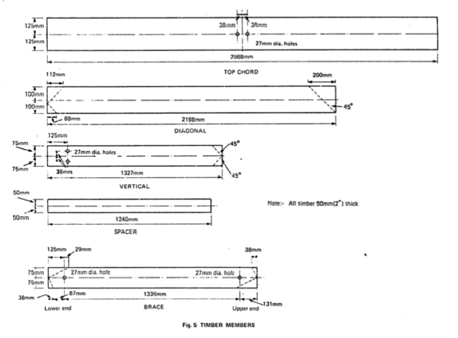
[edit | edit source]All the timber is of 50mm nominal thickness and the depths of the frame members vary from 100 to 250 mm according to their duty (Figure 5). Each timber member comprises two identical pieces of timber which are nailed together back-to-back, except the top chords which are separated by 100 mm spacers. The advantages of this double section design are:
- It facilitates a simple design for the lop joints.
- It increases the stiffness of the top compressive member.
- Knots, checks and other defects in the timber are more easily detected in the thinner sections.
- If one section is weak, the parallel section compensates by taking more load.
Timber specification
[edit | edit source]The bridges in Kenya were made of East African Cypress (Cupressus Lusitanica). This softwood has an average density of 465 kg/m3 at 15 per cent moisture content. Tests made at the University of Nairobi have given a mean value of 8000 N/mm2 for the modulus of elasticity of this timber with a minimum value of 3860 N/mm2.
All the timber members of the frames, except the spacers between the top chords, were visually graded to comply with a standard equal to that of SS grade in British Standard 4978: 1973, Timber grades for structural use.[1] The modulus of elasticity measured at the University of Nairobi suggests that the timber used may be classed as S3 species group: grade SS according to British Standard code of practice CP112, 'The structural use of timber'.[2] The working stresses for this species group and grade are:
| Species Group | Stress |
|---|---|
| Bending | 5.2 N/mm2 |
| Tension | 3.6 N/mm2 |
| Compression parallel to the grain | 5.0 N/mm2 |
| Compression perpendicular to the grain | 1.16 N/mm2 |
| Shear parallel to the grain | 0.66 N/mm2 |
Dry stress values are taken front Table 11a in the British Standard CPI.12[2] as being appropriate in most of Kenya. This may not be the case in other countries, or in some areas of Kenya which have a high humidity for a significant part of the year.
Timber preservation
[edit | edit source]In Nairobi each member of the frame after cutting, was dipped for half an hour in a solution of dieldrin with a small percentage of Pentrachlorophenol. This solution was also painted onto newly exposed surfaces after the holes had been bored for the bolts and dowels. On site, the soil was poisoned to a depth of 300 mm for a distance of one metre behind the bridge abutments to guard against termite attack.
Steel
[edit | edit source]Analysis carried out at the University of Nairobi suggests that the steel used for the Kenyan bridges may be classed as a grade 43, according to British Standard Specification BS 4360: 1972, Specification for weldable structural steels.[3] Values of permissible stresses in the steelwork given by British Standard Specification BS 153: parts 3B and 4: 1972. Specification for steel girder bridges,[4] (assuming that the steel meets the requirements of BS 4360[3]) are:
Permissible stresses for the bottom chord:
| Species Group | Stress |
|---|---|
| Tension | 147 N/mm2 |
| Shear at pin holes | 91 N/mm2 |
| Bearing on pin holes | 193 N/mm2 |
For the steel pins:
| Species Group | Stress |
|---|---|
| Shear | 100 N/mm2 |
| Bearing | 209 N/mm2 |
The frames
[edit | edit source]Figure 2 details the frame on which this bridge design is based. The top horizontal chords are always in compression whereas most diagonal members take both compressive and tensile loads. On the end frames of each truss however, one diagonal member will be permanently in tension and the other in compression. The vertical members are under load only when the frame to which they belong is underneath a superimposed load. The pin locating the end frame to the bridge bearing carries the largest shear force on the truss into the end joint of the frame.
The frame joints
[edit | edit source]Steel dowels are used to join the timber members at each corner of the frame. The two top joints are identical, each consisting of two steel plates (Figure 6) one on each side, through which the dowels pass, penetrating through the horizontal timber member and then into the diagonal. There is no connection through the joint but the two top steel plates are joined when the end plate (Figure 7) is welded across them; a male end plate at one end of the frame and a female at the other.
In the bottom joint, the two diagonal members are not joined by the dowels but each is dowelled to the bottom plates (Figure 8). Again similar plates are used each side of the joint and dowels are driven through them and into the timber from each side. In addition two through-bolts hold the plates in place. The vertical member is restrained by one bolt which also passes through both plates. The top of this member is held between the horizontal chords by two through-bolts. These bolts convey the load from the horizontal chord to the vertical member and so down to the bottom joint of the frame.
The multiple dowel approach to this problem is novel. However, the joints have proved adequate, both in tests carried out at TRRL and at the University of Nairobi.
Bracing
[edit | edit source]Lateral bracing is required since the trusses themselves have no literal stability. Indeed it is difficult to make them hang in one plane between bearings if no lateral support is present. This is because of the forces induced by small variations in:
- The location of the pins in the bottom plate (Figure 8) or the positioning of the plate on assembly of the frame.
- The distance between hole centers in the bottom chords (Figure 3) and
- The squareness of the end plates (Figure 7) that butt together when the frames are assembled end to end.
The vertical cross-bracing shown in Figure I, and the close boarded cross beams provide a large measure of lateral stability. In addition sway bracing is achieved by attaching long wooden members diagonally in a horizontal plane to the underside of the top chords and at bottom chord level. The vertical braces are attached to the top chord using a bracket (Figure 3) and are bolted to the lug on the bottom plate (Figure 8). The lower sway braces may be bolted to the bottom plates with the lug turned through 90° or may be nailed to the wooden spacers between the bottom chords.
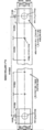
The deck
[edit | edit source]Of several designs tried by Mr Collins for the deck the use of close nailed cross beams was preferred. This puts a larger dead weight on the trusses than using transoms or spaced cross beams but it also increases the bending resistance of the whole bridge. In this design the deck is a stress-carrying part of the assembly and it should be assembled to the trusses as shown in Figure 10. This type of deck is still popular for timber bridges in the USA. The cross beams used in Kenya are 75 mm or 100 mm deep. They are nailed into the spacing timbers between the top chords of the frames and to each other (Figure 10). Running boards, 50 mm deep are attached by nails or coach bolts to the cross beams. These running boards may be replaced when worn without disturbing the structure.
Abutments
[edit | edit source]The bridge abutments are not part of this design. In Kenya, concrete block abutments were used for the bridges but timber or gabion abutments could be used provided suitable bearing surfaces are made to support the brackets (Figure 4) that carry the weight of the bridge. These less permanent types of abutment are adequate for emergency or short-term use, but concrete or masonry abutments may be required to last the full life of a bridge which, with good timber protection, is expected to be in the order of 70 years.
Manufacture
[edit | edit source]Two important aspects of this design are its simplicity and cheapness of manufacture. To this end, all the frames are virtually identical; the only variation being different versions of the bottom plate (Figure 8) according to bracing requirements.
The timber members of the frame are cut to the dimensions shown in Figure 5. It is important that lengths and angles are cut accurately, and for this reason it is recommended that simple jigs are used at this stage. Of equal importance is an assembly jig to ensure that all the frames are assembled to give constant length, depth between centers of the locating pins (1343 mm), and squareness of the end plate. The vertical struts should not project above the top surface of the top chords.
Although the location of the dowel holes in the drilled plates (Figures 6 and 8) is not very critical, a template for the pilot drilling saves time marking out and gives a consistent result. The 40 mm holes in the bottom chords (Figure 3) should be drilled accurately using a template.
It is important that the timber graded for structural use should he kept apart from the non-structural timber, and that the structural members should, be cut so that the ends that are to take the dowels arc free from any defects.
Poor welding could cause the sudden collapse of the structure, so it is strongly recommended that the welders should be qualified according to the appropriate section of BS 153: parts 1 and 2: 1972. Specification for steel girder bridges,[5] or at least be proficient in stress relieving and have test pieces of their work examined for cavitation, penetration, etc.
The Nairobi Workshop
[edit | edit source]The frames used in the Kenyan bridges were made in a workshop in Nairobi, which was equipped with only basic tools. The timber was bought already cut to width and thickness. A hand saw was used to cut the lengths and angles. The steel plate profits were flame cut and the plates were trimmed and the holes drilled in a commercial workshop. Electric hand drills were used to drill the holes in the timber to take the dowels.
The workshop was equipped with:
1 oxyacetylene welding and cutting set
1 cross-cut hand saw
2 portable electric drills
1 jig for culling
1 jig for assembly
vice and various hand tools
The staff consisted of:
2 carpenters
1 welder
5 laborers
The production potential of this workshop was estimated to be about 4 frames per day, sufficient for one average sized bridge per week.
Site erection
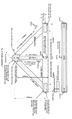
[edit | edit source]The first bridge constructed at Isiolo was built by hand, with each frame being bolted into position in its final place. This was done in the dry season and the method would not be practical for a crossing with deep water or across a ravine. Subsequent bridges were built without support from below using a timber derrick on each abutment with a wire rope stretched between them. The truss was then built up at one abutment and launched across the river; this was done in stages adding further frames until the full truss length was reached (Figure 11).
Normally two trusses would be launched in parallel by this method, thus permitting the timber bracing between the trusses to be constructed at the same time as the frames are put together. If all goes smoothly on site four trusses can be erected in about four hours.
After launching the trusses it is necessary to check all bolts for tightness and then weld up the nuts to prevent theft. For the erection of a bridge about 12 men are required with the following equipment:
2 derricks - timber poles
Wire ropes
4 'Tirfor' or similar winches
Handsaws, hammers, bolt spanners, chisels, hand drill, etc
Welding equipment.
Laboratory tests
[edit | edit source]Laboratory tests at the University Nairobi
[edit | edit source]In developing the design of the bridge a series of tests were carried out at the University of Nairobi. Tests were performed on joints, frames, and a 15m truss. The outcome of these tests is the design shown in Figures 1 to 10.
Laboratory tests at TRRL
[edit | edit source]Frame tests
[edit | edit source]Six bridge frames were made in the TRRL workshops to drawings obtained in Kenya in 1976. East African Cypress was not available in the UK at the time, so timber was chosen from a batch of Hemlock having similar physical properties. This was graded by sight to conform with the same standard used in Nairobi. Steel conforming to grade 43B in British Standard Specification HS 4360:1972[3] was used for all the metal fittings, both plate and round bar.
As a result of the experience of making these frames minor modifications were made to the drawings. These modifications consisted mainly of the addition of tolerances or notes to ensure ease of assembly of the frames on site.
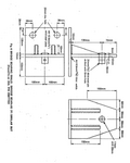
The frames were fitted on to a test rig one at a time and loads were applied to the horizontal members. Measurements of deflections and strains indicated that the horizontal members were weakest when loaded at a point one metre from either end of the flame. It is possible that the running boards on a bridge may break or be butted over this weakest spot on a frame so that the weight from a wheel could be applied there directly and not be distributed by the running board. Four frames were loaded to destruction in this way as shown in Figure 12.
In all four cases the frames failed when a split was opened in one of the horizontal members across the bolt holes at its centre. This split progressed away from the load point under further loading until it broke out near the end of the member, either into the dowel holes or into the lower surface. The failure occurred gradually and in all cases the frame continued to sustain the load that caused the horizontal member to split. A greater load, or several applications of the same load, were required to cause the second horizontal member to fail. The moisture content of the timbers measured with a resistance meter ranged from 15 per cent 0.17 per cent. The results arc summarized in Table 1.
For this load test, the simulated cross beams were spaced 25 mm apart like those on the first bridge built at Isiolo. The later, close-boarded cross beam design, with the beams also nailed together, would give better distribution of the load and also more strength to the structure. This is discussed in more detail in Section 8.

The horizontal members of these frames failed because the bolts that transferred the load to the vertical members initiated the split, which then spread until it broke out. Although each frame sustained a useful load before failure, there was some indication that failure would have occurred at a lower load after many more reversals. For example the fourth frame sustained a load of 90 kN when first loaded and failed at 80 kN on a subsequent loading.
In order to obtain better use of the strength of the horizontal members of the frame, the four failed units were repaired using new timber for the horizontals. The two bolts that caused the splitting were removed from the holes on the centre line of the horizontal members and placed 60 mm from the lower edge as shown in Figure 13.
The four frames were loaded as before. In all four cases failure occurred when the fibres ruptured in tension below the applied load due to the bending stress at that point. Neither the two bolts in the position, nor the empty holes on the centre line, caused splitting to weaken the horizontal member. The loading of these frames is summarized in Table 2 below.
In none of these tests was there any sign of failure in any of the dowelled joints.

Three frame truss tests
[edit | edit source]Three frames were assembled with steel chords to form a truss and this was suspended on brackets placed on tripods. The truss would not hang in a vertical plane but bowed to one side. This was caused by a lack of squareness in the end plates of the frames, although the worst individual discrepancy was only 2º. The truss was held straight while simulated cross beams and a running board 200 mm x 50 mm were nailed on. When released the truss bowed again.
Rolling loads up to 30 kN were applied to the truss and strains were measured in all the members. The analysis of these strains showed that there was very poor distribution of the load among the members of the truss; for example one steel chord of a pair tended to take all the tension.
Conclusions and recommendations drawn from the tests at TRRL
[edit | edit source](i) TIIC dowelled joints showed no signs of weakness during these nests.
(ii) Strains are not well distributed in the frame unless special care is taken during manufacture to ensure symmetry, and squareness of the ends. It is recommended that care should be taken to cut the horizontal members to the same length and to line them up carefully on assembly so that the end plates (Figure 7) are square when welded. It is also important to position the bottom plates (Figure 8) so that the two 38mm input diameter pins line up and are precisely on the centre line of the frame.
(iii) Placing the two bolts on the centreline of the horizontal members causes unnecessary weakening. This may be avoided by positioning these bolts 60 mm from the lower edge of these members.
(iv) The spacing timber between the top chords could be a useful structural member if it were continuous between the top joints instead of being in two parts, one each side of the vertical members. Re-positioning the two bolts mentioned in (m) above makes it possible to shorten the vertical strut by 50 mm and so permit the spacing timber to run continuously from end joint to end joint above the strut.
Site tests in Kenya in 1976
[edit | edit source]Tests at Isiolo, 1976
[edit | edit source]A bridge at Isiolo was inspected by TRRL staff in 1976, two years after it had been built. It had a span of 15 metres, four trusses, and the cross beams had air spaces between them. An empty Leyland Super Hippo three axle lorry was driven slowly backwards and forwards over the bridge and strain readings were taken at 25 positions using a Demec gauge 200 mm long. The strains were measured as nearly as possible on the neutral axes of the more highly stressed members, and away from knots in the timber, which could have affected the readings.
The live load applied to the bridge was as shown in Figure 14. The strains measured are shown in Table 3 with the corresponding calculated stresses, assuming a modulus of elasticity (E) for steel of 180 kN/mm2 and for the timber 8 kN/mm2. The figures recorded were the maximum readings of the gauge for each member as the load passed over the bridge. Table 3 shows the mean of these and the highest for corresponding members on parallel trusses. For comparison, the theoretical values are shown. These were obtained using an ICL computer program, Analysis of Plane Frames and Grids, System 46. It was assumed that the plated joints are rigid and all other pinned.
The correlation between the figures in columns 2 and 3 is interesting in that the stresses from the measured strains (2) are lower than the theoretical values (3) for the steel chords. There is a good correlation for all four diagonals, considering the variations in the value of E of different samples within a timber grade. The measured value in the top chord, however, falls far short of the theoretical figure and this, together with somewhat lower values for the bottom chords. suggests that the deck was contributing extra strength to the structure. For the purposes of calculating the forces in the bridge members. the contribution of the cross beams, running boards and packing between the top chords of each frame was ignored because it was thought to be small, difficult to quantify and unreliable. The suggested modification to the packing between the top chords (see Section 5.2.3) would make it a continuous member between the top joints and so more likely to share the compression in the top chords.

The bridge at Isiolo failed some years after these tests were performed. The cause of failure is not known definitively. but the circumstantial evidence is that the bridge was repeatedly overloaded by heavy vehicles.
Tests at Nyeri, 1976
[edit | edit source]The bridge at Nyeri (Plate 1) is a skew bridge with four trusses of seven frames designed to carry loads up to 10 tonnes. Close-nailed cross beams support the running boards. The strain measurements shown in Table 4 were obtained by Mr. Collins and refer to load tests carried out in 1976 using a lorry with a nominal 5 tonne rear axle, 2 tonne front axle, and a wheelbase of 3.05 metres. The chords were numbered as shown in Figure 15.
The strains measured in chords 7 and 8 are low and this may be due to small variations in the dimensions of frames or steel chords, but as these two chords are adjacent, the frame common to both may be non-standard. There is also a possibility that the vertical cross bracing between the trusses was causing a side load at the point where the chords join. The summations shown in Table 4 simply indicate that the load was centred well across the bridge and that three of the trusses were equally loaded, but the truss containing the two lightly loaded chords carried less weight than the others.

An estimate of the stresses in the bottom chords may be obtained by treating the structure as a series of rigid frames pin-jointed to each other, assuming even distribution between the trusses of the loads due to the passage of the lorry and ignoring the effect of the deck. Maximum tension in chord M1 occurs with the lorry positioned as shown in Figure 15a. The steel chords at Nyeri were 4 in x ¼ in (101.6 mm x 6.35 mm) in section with ¼ in diameter (6.35 mm) nail holes. The theoretical maximum stress in the chords, assuming even distribution of stress, was calculated as 50.3 N/mm2 at the holes and the maximum between the holes 47.2 N/mm2. The strains were measured over a length of 200 mm between the holes. Here, as at Isiolo, the mean stress calculated from the measured strains - 28.7 N/mm2 - is less than the theoretical value - 47.2 N/mm2, the ratio being 0.6.
Nyeri tests in 1979 - steel chords
[edit | edit source]The Nyeri bridge was again inspected by TRRL staff in 1979. On this occasion strains were measured in the steel chords as before, hut strains were also measured in the top chords of the end frames. The lorry used for this test was a Bedford J6 with a measured rear axle weight of 6,400 kg, front axle weight of 1,600 kg and a wheelbase measuring 4.0 metres. Table 5 shows the measured strains and resultant stresses in the bottom chords.

Readings on chord 3 were not reproducible. This was due either to a defective demec disc or to the way it was glued to the steel chord. The maximum resultant stress from measured strains was 49.5 N/mm2 (chord 9). This is one-third of the permissible tensile stress for the steel chord. when the bridge was loaded to 80 per cent of the notified limit. This maximum resultant stress and the mean stress derived from the measured strains is shown in Table 6 with the corresponding theoretical figure, calculated as in Section 6.2, together with similar results from the other two tests.
Summary of the strain tests on the steel chords
[edit | edit source]In all the tests the measured maximum stress (a) was lower than was expected (b), and by a similar amount in each case. This is due to the contribution of the deck, which was ignored in the calculation of the theoretical stresses. If the two tests at Nyeri were carried out with similar accuracy it would seem that the contribution of the deck diminished between 1970 and 1979. This, if true, may be attributed to bedding in of the cross beams since a close examination of the bridge disclosed no loose joints.

Nyeri tests in 1979 - timber top chord
[edit | edit source]It is thought that the first bridge built at Isiolo failed when the horizontal top chords of the end frames broke, due to being repeatedly overloaded. Consequently strain measurements were taken with a demec gauge on the lower faces of four of the top chords of the bridge at Nyeri in 1979 (Figure 16). The results are shown in Table 7.

The maximum stress in this horizontal member comprises compression due to self weight of the trusses and deck plus the applied load, coupled with bending stress due to the heavier axle load as it passes over the frame.
On the basis of the computer program[6] the calculated compressive axial load on the timber top chords of the four end frames due to the weight of the trusses and deck was 33.5 kN, and the compressive load due to the applied load was 71.7 kN, totalling 105.2 kN. The combined area of the top members was 0.1 m2. Thus if the contributed anything to the bending resistance of the bridge, the mean compressive stress in the horizontals would be 1.05 N/mm2.
If the top chord of a frame were pin-jointed at each end at the centre. The bending moment on it 1 metre from the end due to the weight of the 6,400 kg axle at that point would be 1887 Nm. if it were pin jointed at the centre and built in at each end, the bending moment at that point would be 1670 Nm. Accepting that the appropriate value is between these two, and as they are similar, taking the mean value 1779 Nm, the extreme fibre stress in the top chord due to bending 1 metre from the end is 3.42 N/mm2 compression at the top and tension at the bottom. Combining this with the axial compression, the expected maximum stress: in this member ignoring the structural contribution of the deck, is 4.47 N/mm2 compression at the top and 2.37 N/mm2 tension at the bottom.
To summarize:
| Location | Bending Stress | Axial Comp. Stress | Resultant Stress |
|---|---|---|---|
| Top | |||
| Bottom |
The deck may be thought to relieve the top chords of a small part of the bending stress and a large part of the compressive stress. The net result of this would be little change in the tensile stress but a reduction in the compressive stress.
For example, if the deck absorbs 50 per cent of the compressive stress and 20 per cent of the bending stress, these figures become:
| Location | Bending Stress | Axial Comp. Stress | Resultant Stress |
|---|---|---|---|
| Top | |||
| Bottom |
The stresses calculated from the measured strains at the bottom of the members from Table 7 are:
The permissible working stresses for the timber are:
Hence without the contribution of the deck, the resultant compressive stress (a) in the top of the top chords would be very close to the permissible stress (b) with the bridge loaded to only 80 per cent of its rated capacity of 10 tonnes. Strain measurements on the bottom chords and the top chords at Isiolo suggest that the deck relieves the trusses of a significant proportion of the expected stresses, but measurements of the tensile strains on the lower faces of the end top chords do not support or refute this, as they have been shown to change little if the deck takes a proportion of the stress. Compare the theoretical stress ignoring the deck with the theoretical stress counting on the deck for some help (d)and the stress from the measured strain (e). It is unfortunate that it was not possible to measure the extreme fibre strains on top of the top chords because of the deck timbers.
Loading and service recommendations
[edit | edit source]When deciding the strength required of a bridge it is important to know not only the current traffic conditions, but also the likely flows and maximum loads during the projected life of the structure. Although additional trusses may be added after a bridge of this type has been built, this would be considerably more expensive than budding them in initially, when the cost of two more trusses would almost certainly be less than 15 per cent of the total cost of a bridge including abutments.
There is of course no guarantee that stipulated weight limits for vehicles will be obeyed. In most circumstances It must be assumed that the largest lorries in an area will cross a bridge unless prevented by a permanent physical obstacle.

Table 8 above showing the number of trusses required for various loading duties and spans, using
timber of the grade described in Section 3.1.1. was provided by the designer. Calculations at TRRL support these figures provided that the deck is accepted as a stress sharing part of the structure. Experimental results suggest that this is so, but it is the opinion of engineers in Bridges Division of TRRL and the Building Research Establishment, Princes Risborough that it would be unwise to rely on any contribution from the deck.
An essential feature of this design is that the deck absorbs some of the axial compressive load that would otherwise be born by the top chords of the trusses, but more importantly that the deck also distributes axle loads along these horizontals. If this is disregarded, the most severe loading on the structure is when a two axle vehicle is near the centre of a two truss bridge, at a point to cause maximum bending moment on the trusses, and hence maximum compressive load on the top chords in the centre. If the heavy axle is about a quarter of the way across the centre frame, there is also a severe bending moment on the horizontal members of that frame (see Figure 17). If the heavy axle is assumed to apply a point load directly onto the trusses. the combined bending and compressive stresses in the central top chords at the upper face would exceed the permissible compressive stress by about 200 per cent. A possible way to reduce this theoretical overload to less than i0 per cent would be to replace the two horizontal, members per frame measuring 250 mm by 50 mm with four others measuring 300 mm by 50 mm. This would also entail changing the joint at the top of theoretical member and using two steel plates with dowels or bolts.
Materials, both timber and steel, vary in quality above and be!ow that specified here. It is recommended that an engineer in charge should check the adequacy of the material he proposes to use, should it vary in any way from this. The items that should be checked are:
- steel chords for tension
- lower pins for bearing stress
- end diagonals for tension
- horizontal members for combined stresses
- moisture content of timber in the proposed location.
Discussion
[edit | edit source]Wherever suitable timber is available this modular design of timber bridge is relatively cheap to build. The tests made, and the field performance of bridges built to this design, indicate that the design is basically sound and that it is suitable for use for spans in the range 12m to 24m, at the loadings listed in Table 7. However, calculations ignoring the structural effect of the deck suggest that some horizontal members may be grossly overstressed. Light vehicles can be carried over spans greater than 24m, but at such spans it may be necessary to take measures to improve the lateral stability of the bridge, and it would also probably be desirable to enlarge the size of the basic frame and the other parts proportionately.
Apart from the cheapness of the bridge, its other advantages are:
- the materials and skills required to build the bridge are available locally in most developing countries,
- the modular design permits prefabrication of the frames in simple workshops,
- the frames may he stored for emergency use, and can be assembled to make a bridge on
prepared abutments very quickly, - the bridge components are small enough and light enough to be air-freighted to a remote site if
a bridge is required urgently.
The disadvantages of the design are:
i) because the trusses arc located beneath the bridge deck it is necessary to raise the road level, and hence the abutments and approaches at least 2.5m above the expected maximum high water level in a river being bridged (if floating debris is a hazard it may he necessary to raise the bridge and approaches even further).
ii) spans must be a multiple of 3m, hence if it is being used to replace a different type of bridge that has been washed away leaving the abutments intact. it may he necessary to modify the abutments so that the new bridge bearings can be located at a multiple of 3m apart.
iii) more substantial abutments are required for this bridge than for other types of emergency bridging, such as the Bailey Bridge.
There are also several comparatively low cost alternatives to this design that should not be overlooked:
In countries where locally-grown timber is available in the requisite sizes, whole log, or rectangular section timber beam bridges can be built at low cost over spans of up to 10m, or up to 15m if hardwoods are available. If the site conditions are favourable for the erection of piers, multispan bridges with timber beam decks will be the cheapest solution, as has been adopted in the Kenya Rural Access Roads Programme.[9] This type of solution may he economical even if steel girders are used to span between the piers.
Where longer spans are unavoidable other types of timber truss bridge have given excellent service, the Town lattice girder bridge and the Howe truss bridge[10] have been used successfully in the United States of America for over a century, as have variations of these designs. Both of these designs utilise many identical struts and ties, which may be cut and prepared away from the erection site. The surviving bridges of this type are mostly 'through' bridges which are roofed. In wet climates this greatly extends the life of the bridge.
Bridges constructed with other materials such as reinforced concrete, plain concrete (for arch bridges), rolled steel joists with timber or concrete decks, and prefabricated steel (such as Bailey and Callender Hamilton bridges) will normally be the choice for spans greater than 12m where permanent or semi-permanent bridges are required. They are however likely to be between two and four times as expensive as the Kenya modular timber bridge (see Appendix), and access problems may rule out the use of large rolled steel joists in remote locations. Simple reinforced concrete slab bridges arc however very satisfactory for short spans and many are built on rural roads in Kenya each year as in other developing countries. If the vaulted arch technique is used, as in China. plain concrete can be utilised to bridge substantial spans, but this solution requires complicated shuttering and is rarely adopted elsewhere.
It has not been possible to investigate the effect of fatigue or wear on this design of timber bridge,hence predictions of its life can be only very tentative. For instance the performance of the dowelled joints after thousands of reversals of load near to the permissible limit is unknown. Similarly the long term durability of the relatively thin timber sections in the frames is problematical, although expert opinion (at the Princes Risborough Building Research Station) puts the expected life at 20 years or more provided the average timber moisture content is less than 20 per cent and regular inspection and maintenance procedures are employed.
The oldest bridge of this design in existence is that at Nyeri, which is in good condition, but which has not carried more than a handful of commercial vehicles per day and a similar number of light vehicles throughout its life. The available evidence therefore limits the known safe utilisation of this design to very lightly trafficked roads carrying not more than 1000 heavy vehicles per year if a life of 20 years is required, or to somewhat more heavily trafficked roads carrying say 5000 heavy vehicles a year if a life of less than five years is acceptable. The numbers of cars and light commercial vehicles are not likely to have an appreciable affect on the life of this type of bridge.
Whatever the application selected for this design of bridge. it is strongly recommended that each application is checked by a competent engineer and that thorough structural inspections of the bridge are made at least annually.
Conclusions
[edit | edit source]This assessment for the Kenya low cost module timber bridge has shown that the design is generally sound and well balanced with the possible reservation mentioned above concerning the contribution of the deck. More specifically it is concluded that:
a) the unusual dowelled joints used to make the frames showed no sign of weakness during tests or in service.
b) stresses and strains arc well distributed in the trusses only if special care is taken during manufacture of the frames to ensure dimensional integrity and squareness on the ends.
c) the frames can be strengthened by repositioning the two central bolts in the horizontal member and by using a continuous spacer between the two pieces of timber which comprise this member.
d) the close boarded deck makes a significant contribution to the strength of the bridges examined in Kenya.
e) it is a relatively cheap structure and is most useful for bridge spans from 12 to 24 metres on low volume roads,
f) with suitable regular maintenance the life of a bridge is expected to be at least 20 years.
Acknowledgements
[edit | edit source]The work described in this report was carried out in the Overseas Unit of TRRL, the University of Nairobi and the Kenyan Ministry of Natural Resources. The co-operation of all those who assisted with the supply of information is gratefully acknowledged: in particular Mr. J. E. Collins, who designed the bridge, and Mr R S Mansfield, who undertook the inspections in 1976.
Many helpful suggestions were made by members of the Bridge Design Division, TRRL and the Building Research Establishment at Princes Risborough.
References
[edit | edit source]- ↑ BRITISH STANDARDS INSTITUTION. Specification for timber grades for structural use. British Standard BS 4978: 1973, London (British Standards Institution).
- ↑ 2.0 2.1 BRITISH STANDARDS INSTITUTION. The structural use of timber. Code of Practice CPI12: part 2, amendment slip No. I, September 1973, London (British Standards Institution)
- ↑ 3.0 3.1 3.2 BRITISH STANDARDS INSTITUTION. Specification for.weldable structural steels. British Standard BS 4360: 1972, London (British Standards Institution).
- ↑ BRITISH STANDARDS INSTITUTION.. Specification for steel girder bridges. British Standard BS 153 Parts 3B and 4: 1972, London (British Standards Institution).
- ↑ BRITISH STANDARDS INSTITUTION. Specification for steel girder bridges. British Standard BS 153 Parts 1 and 2: 1972. London (British Standards Institution).
- ↑ INTERNATIONAL COMPUTERS LTD. System 4. Analysis bf.plrne frames and grids (6) 4517, I972 (Technical Publications Service).
- ↑ BRITISH STANDARDS INSTITUTION. Specification for steel girder bridges. British Standard BF 153 Part 3A: 1972, London (Uritish Standards Institution).
- ↑ THE AMERICAN ASSOCIATION OF STATE HIGHWAY OFFICIALS. Standard Specification for Highway Bridges. Washington 1979 (The American Association of State Highway Officials).
- ↑ THE WORLD BANK TRANSPORTATION DEPARTMENT. Kenya Rural access Roads programme IBRD/MOW/ODM Technology Unit. Final Report Volume 11. Technical Manual. Nairobi, 1978.
- ↑ AMERICAN SOCIETY OF CIVIL ENGINEERS. American Wooden Bridges. ASCE Historical publication No. 4. New York, 1976.
- INTERNATIONAL COMPUTERS LTD. System 4. Analysis of plane frames and grids (6) 4517, 1972 (Technical Publications Service).
-
-
-
-
-
-
-
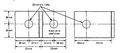 Figure 9: Top Bracing Connection
 -
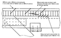 Figure 10: Detail of Deck
 -
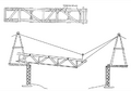 Figure 11: Launching A Pair of Trusses
 -
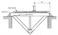 Figure 12: Test Loading A Single Frame
 -
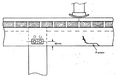 Figure 13: Frame Modifications
 -
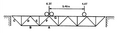 Figure 14: Bridge Test at Isiolo
 -
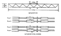 Figure 15: Bridget Tests at Nyeri - Bottom Chords
 -
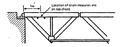 Figure 16: Bridge Tests at Nyeri - Top Chords
 -
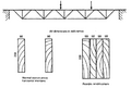 Figure 17: Illustration of Theoretical Overload Condition
 -
 Plate 1: The Four Truss Bridge at Nyeri


Appendix: Bridge costs
[edit | edit source]Each site will impose conditions on bridge costs, which for a given span may vary by a large factor. Variations in cost due to non-typical foundations and abutments are not considered here. As with the design, the cost of a bridge must be determined for each individual circumstance.
Below is a simple breakdown of costs for this design of truss and deck, itemised so that unit costs applicable elsewhere may be inserted easily to build up the total cost. The prices quoted are the commercial prices applicable in Kenya at the end of 1979, expressed in Kenyan shillings.
Material
Building grade Cypress 100 x 50 mm - 8/- - per metre or 1600/- per m3. Assuming 30 per cent excess for large sections and 20 per cent excess for graded timber, the price becomes 2500/- per m3. Quantities are for a bridge with four trusses.
| Deck | 0.4m3 per metre length @ 1600/- | 640/- |
| Frames | 0.28m3 per metre length @ 2500/- | 700/- |
| Steel plate and dowels | 51 kg per metre length @ 5.3/- | 270/- |
| Steel chords | 34 kg per metre length @ 5.3/- | 180/- |
| Nails and bolts | per metre length | 80/- |
| Total | per metre length | 1870/- |
| for 18 metres | 33660/- |
| 8 bearings | 44kg @ 5.3/- | 233/- |
| Paint, wood preservatives, soil poison | 2000/- | |
| 2233/- + 33660/- = 35893/- |
Wages
Wages for the staff listed in Section 4.1 allowing 2 weeks for manufacture of jigsand frames.
| 5 labourers 10 days @ 50/- per day | 1500/- | |
| 3 craftsmen 10 days @ 70 /- per day | 2100/- | |
| 3600/- | 3600/- | |
| Similar team for erection - 5 days | 1800/- | 1800/- |
| 5400/- | ||
| 33 per cent overheads on labour | 1800/- | 1800/- |
| 7200/- | ||
| Labour for manufacture and erection | 7200 |
Transport
2 lorries to deliver materials to site
| 1 day @ 1000/- each including drivers | 2000/- | ||
| 1 lorry for site work and return of equipment 4 days @1000/- | |||
| 4 days @ 1000/- | 4000/- | ||
| 6000/- | 6000/- | ||
| Total cost of manufacture and erection for 18m span | 49093/- |
This excludes the cost of the engineer and clerical staff.
For comparison purposes the cost of manufacture only is:
| Materials | 35893/- | |
| Labour | 3600/- | |
| Total | 39493/- |
In approximate terms both Callender Hamilton and Bailey type bridges cost about four times this sum ex works, or about five times delivered by sea to Mombasa.
Steel RSJ beams, if available at the same price as the small sections referred to in Section 3.2, would cost about 35,000/-. If imported the cost would be about 50,000/-. and in addition some 15m3 of reinforced concrete would be required for the deck, costing about 54,000/-. If cement were not available a deck could be made with 8m3 of timber, costing about 13,000/-. Transport costs to; the site could be high for two steel beams 20 metres long, weighing 3 tons each. Costs of these four types of bridge are sumarised in Table 9.
| Kenya timber bridge | 40000/- |
| Bailey/Callender Hamilton | 200000/- |
| RSJ with concrete deck | 85000 - 100000/- |
| RSJ with wooden deck | 48000 - 63000/- |
| Authors | |
|---|---|
| License | CC-BY-SA-3.0 |
| Cite as | A.severs, A.Dacho, CBaechler, B. Dawney, Dloates (2010–2025). "The Kenyan Low Cost Modular Timber Bridge". Appropedia. Retrieved July 26, 2026. |