Steps 4-6 are just for the spool holder. If you do not want a spool holder (which is very, very recommended to have with any 3D printer) or already have one, you can skip those steps.
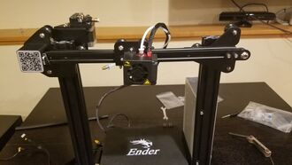
Putting on the X-axis motor to the Ender 3 frameTake the X-axis motor with the QR code facing you, and place it on top of the Ender 3 frame. The QR code motor should be attached to the beam with the Z-axis motor and the mounting brace should be on the power supply beam.
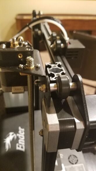
Placing the X-axis motor through the Z-axis threaded rodLine up the gold thread on the X-axis motor with the Z-axis threaded rod. Then press down on the X-axis motor while spinning the Z-axis motor coupling, not the Z-axis threaded rod because that is greased, counter-clockwise. Once the golden thread grasps it, stop pushing down on the X-axis motor. Continue spinning the motor coupling until the top of the beams are cleared of the rollers.
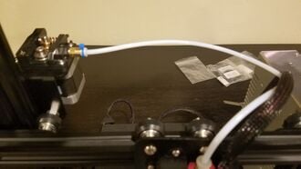
Attach the teflon tube to the brass nut sticking out of the extruder motor with the blue plastic connectorConnect the teflon tube from the extruder head to the extruder motor brass nut. Once connected, put the blue plastic connector onto it.
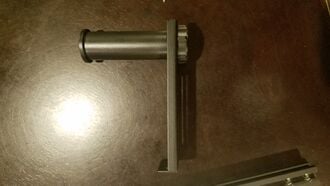
Attaching the plastic tube, plastic nut, and the sheet metalbracket togetherTake the plastic tube and put the short end through the sheet metal bracket hole. Then, attach the plastic nut to the plastic tube through the sheet metal.
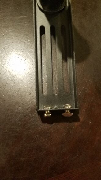
Attaching M5x8 screws and M5 t-nut to the sheet metal bracketPlace the two M5x8 screws through the bottom of the sheet metal bracket, and then loosely attach the one M5 t-nut to the bottom of each screws
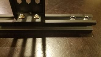
Attaching the sheet metal bracket to the 20x20 beam with 4 pre-drilled holesAttach the sheet metal bracket to the 20x20 beam with 4 pre-drilled holes. Attach it to the side with wider holes on top.
Attach the 20x20 to the top of the frame using the four M5x25 screws. It does not matter the orientation, but it may make more sense if you have the plastic tube facing the back of the printer.
Put on the end caps to the 20x20 beamAttach the two end caps to both ends of the 20x20 with four pre-drilled holes.
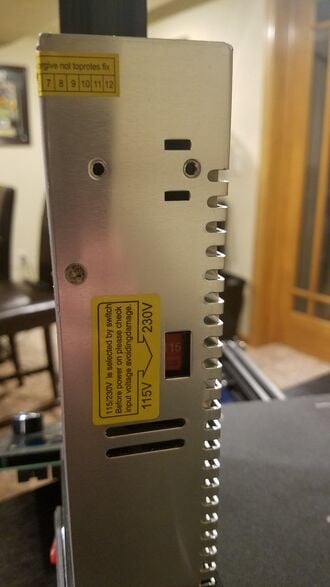
Change the 230V to the 115V for the power supplyLook behind the power supply, and change the 230V to 115V.


.jpg)


