
DC Power Monitor For Medical Devices

In this group project, we built a power monitor capable of accurately tracking Voltage, Current and Power data accurately over a long period of time, measuring voltage from 0-48V and current from 0-10A. Our device stored the data collected in text files on a SD card, which can be imported into programs like Excel to generate graphs and other data plots. Our device incorporated various other features, including a voltage alarm, an active clock, and adjustable time between data logs. During the showcase event, we were awarded the "Overall Showcase Top Design" and "Top Design in Category" awards among all first-year engineering students for excellence in engineering design methodology and execution.
Background
[edit | edit source]This project was created for the ES1050 Engineering Design Class at Western University. For our project, we were tasked with creating a low-cost DC Power Monitor using off the shelf components to monitor the power draw of medical devices from clinics in rural countries. These medical devices often use batteries or solar power for electricity due to the unreliable grid power causing frequent power outages. Our device will be used to predict the amount of power required to run certain devices over certain periods of time, ensuring the patients are able to receive reliable treatment without the risk of their medical devices losing power. The data from the power monitor would allow staff at these facilities to budget their power accurately, and conduct preventative maintenance to ensure reliable operation of the medical devices.
Problem Statement
[edit | edit source]Medical staff in rural areas require a low cost power monitor that measures DC power data from portable batteries and solar panel power sources. This data will be used to understand the power consumption of their medical devices and track power irregularities to predict the amount of power required for each device while doing preventative maintenance on the power sources. For that reason, these power monitors must be reliable, easily deployable and easy to repair and maintain.
Constraints and Objectives
[edit | edit source]| Objective | Description |
|---|---|
| Minimize Cost | Tally up the costs of all the parts and ideally it is under $100, or try to lower the cost as much as possible without affecting the functionality |
| Maximize Accessibility | Give the device to multiple random people and ask in a survey how easy it was to figure out how to operate it from a scale of 1-10 |
| Minimize Data Loss | Track the amount of data that can be held by the device and for how long(at least one week), along with the number of backup methods the device has(at least 2). |
| Minimize Mantenance | Count the number of different tasks need to be completed over the course of a month to keep the device always operational, and minimize it as much as possible(ideally less than one mantenance task a week) |
| Maximize Safety | Conform to as many worldwide safety standards as possible, ensuring that all parts at least conform basic Canadian safety standards(CSA and UL) |
| Maximize Adjustability | Change the intervals from 5 to 10s to 15s etc. and run each for 1 min. See if the SD card has appropriate readings. If done correctly the first trial should have 20 results, the second 6, and the third one 4 respectively |
| Maximize Repairability | Time how long it takes to replace every part in the device, and modify the design to minimize the time required. Ideally, most parts should be able to be changed within 10 minutes. |
| Minimize Environmental Impact | Try to have at least 80% of the parts inside be reusable, and use recyclable plastic for the case. Additionally, use the carbon footprint calculator and modify the design to minimize the carbon footprint of the device |
| Constraint | Description/How to Measure |
|---|---|
| All Parts must be easily accessible to to the client | Have client confirm they can aquire 100% of parts from the bill of materials with ease, and find alternatives to any they can't |
| Measure DC Current of 12V to 48V and 5-10A accurately | Conduct tests/surveys with others, asking for their feedback about how easily they could transport it on their own. It must receive a passing grade from all survey participants. |
| Device must have a handheld and portable design | Use multimeter and live serial output to monitor the readings and ensure they are within 5% accuracy for the provided ranges. |
| Save data on non-volatile memory | Try saving data and turning off the device at least 10 times, and then turning on the device again and ensure 100% of the data has been preserved |
| Add All Possible Compatible connections and power standards | Research all possible solar panel and battery connection types with medical devices, and confirm this information with at least one worker at a medical clinic or the client. Additionally, confirm the power monitor works with the power standard required(AC or DC current) |
| Ensure Connectivity is compatible with their devices(any devices using android or windows) | Test all possible devices(Ex. Phones, laptops, tablets) they may have access to and ensure all functions of the power monitor work on said devices |
| Ensure device is durable enough for the challenging environment | Test device for at least 24 hours within a high temperature, high dust environment and check to ensure all its functions are working afterward. |
| Protection against power instability | Ensure the device is able to protect itself against over current or over voltage. Ensure it is still functional after sustaining higher than rated voltage or higher than rated current. Additionally, the device should alert the user whenever there is an issue for safety. |
| Device should not have a significant effect on the power moving through the device | We can test the efficiency by measuring current and voltage manually with a multimeter, with and without the power monitor, and ensure these values are within 5% of each other to be acceptable |
Iteration and Prototyping
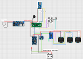
[edit | edit source]Early ideas for the device included creating an app to connect to the power monitoring device, allowing it to control the functionality and retrieve the power data. However, that solution would have inhibited the ease of use of the device, resulting in us creating a power monitor that didn't require another device to operate. The power data would be stored locally on an SD card, which can be imported into Excel or any other data analysis software. The device would be controlled using physical buttons and a built in display to show live data, which included time, power data, and whether or not the power monitor is recording data.
-
-
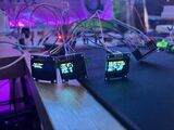 Testing the displays and modules before assembly
 -
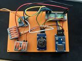 Internal base with the main electronics
 -
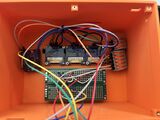 Internal top shell with the buttons and displays


Final Product
[edit | edit source]Our final design implemented a 5 button navigation system, along with 3 mini OLED displays to effectively display all relevant information. Due to limitations with shipping times, we used a INA226 instead of the INA228 to test the design, resulting in the voltage range being 0-36V instead of the desired 0-48V range. However, the design could be easily modified to incorporate the INA228 sensor with minor code modifications. Additional features included:
- real time clock which can be manually set
- voltage warning system with manual adjustment of voltage limits
- random power off data safety
- multiple power source options(External battery/power supply, or power directly from medical device)
- adjustable time in between data logs
Bill of Materials
[edit | edit source]| Main Components | |||
|---|---|---|---|
| Item Description | Quantity | Unit Cost (CAD) | Total Cost (CAD) |
| INA228 | 1 | 22.72 | 22.72 |
| DS3231 Real Time Clock Module | 1 | 10.65 | 10.65 |
| cr1220 Coincell battery | 1 | 8.99 | 8.99 |
| Buzzer Multipack | 1 | 8.99 | 8.99 |
| Push Buttons Multipack | 1 | 13.88 | 13.88 |
| OLED Displays(3 Pack) | 1 | 18.99 | 18.99 |
| Wire-30cm | 3 | 0.3 | 0.90 |
| Raspberry Pi Pico | 1 | 13.95 | 13.95 |
| 10A Fuse | 1 | 1.41 | 1.41 |
| Inline Fuse Holder | 1 | 5.43 | 5.43 |
| TCA9548A Multiplexer | 1 | 11.69 | 11.69 |
| SD Card Module with 3.3V to 5V Converter | 1 | 8.9 | 8.90 |
| M2 Heat Set Insert | 1 | 8.99 | 8.99 |
| M2 Screws | 1 | 8.99 | 8.99 |
| Power Options | |||
|---|---|---|---|
| Item Description | Quantity | Unit cost (CAD) | Total Cost (CAD) |
| Inline Power | |||
| DC Power Connector (Female) | 1 | 7.7 | 7.70 |
| 48V to 5V Buck Converter | 1 | 21.26 | 21.26 |
| Grand Total | 29.16 | ||
| DC Power Supply | |||
| DC Power Connector (Female) | 1 | 7.7 | 7.70 |
| 5V 1A DC Power Supply | 1 | 12.99 | 12.99 |
| Grand Total | 20.89 | ||
| Battery Power | |||
| 3x AA Battery Box | 1 | 11.99 | 11.99 |
| Grand Total | 12.19 | ||
Operation
[edit | edit source]
Warning: Device will NOT Power on without SD Card installed. Ensure the SD Card is installed before powering on!
- To install the SD Card, locate the slot at the bottom right on the front of the device
- Slide the SD Card into the device in the shown orientation (gold pins facing down and away from you) and gently slide it in until you hear a click
- Release the SD Card and it should be slotted in correctly

Connecting to Device for Measurement
- To measure data from a medical/DC powered device, the device must be wired with an adapter between its DC power source and itself.
- As seen in the photo, this adapter must be placed in between the device and the adapter. Ensure the polarity is correct, with positive being red and negative being white.
- On the back of the device, locate the power measurement port and connect the other end of the adapter to the power monitor
Battery Box Connection
- Slide the battery box into the left channel of the device as shown:
- Connect the battery box to the device using the cable on the side of the channel. It will click into place only in one direction
- Flick the switch on the side of the battery box to power on the device
5V Power Supply Connection
- Slide the power supply module into the left channel of the device as shown:
- Connect the power supply module to the device using the cable on the side of the channel. It will click into place only in one direction
- Plug in the larger side of the DC Power supply into the wall, and plug in the DC barrel jack side into he power supply module

Screens
Screen 1: Displays main menu, allowing the user to change settings and monitor exact sensor values
Screen 2: Locked to display current power data, rounded to 2 decimal places at all times
Screen 3: Locked to display date, time and log status at all times
Basic Device Controls
UP(Top Yellow Button) - Moves selection up one in menus, or increases the value of selected setting by one in settings
Down(Bottom Yellow Button)- Moves selection down one in menus, or decreases the value of selected setting by one in settings
Select(Green Button)- enters into the highlighted menu in settings(denoted by an arrow) or changes the selection of which parameter to change in settings(also indicated by an arrow)
Exit(Blue Button)- Returns back to the homepage no matter which menu is currently displayed
Rec(Red Button)- Starts and stops data logging on the device
Recording Data
- To start or stop recording data click the Red button “Rec”
- On the second display there is a Logging variable, which is “OFF” it is not recording and “ON” meaning it is recording.

Menu
- When powered on the 1st display will show Figure 5
- The Arrow on the right side indicates which option is currently selected. Pressing the up and down buttons move the selection arrow up or down
- Pressing select will the Select button will enter into the menu currently selected by the arrow menu

Set Date
- On the main menu scroll down by clicking the down button to settings until the arrow reaches “settings”
- Click select button once on “Setting”, (if you want to go back to the main menu click exit button)
- Use the down button to scroll down until the arrow selects “Date” and press the Select button
- The current date that is displayed will appear by “year:month:date”
- Use the Select button to cycle through the different values, with an arrow underneath “^” is indicating what period is currently selected
- Once you select the desired value to change, use the Up and Down buttons to increase or decrease the value by increments of 1
- Once finished and your desired date is displayed on the Third Display, click exit to go back to the main menu.

Set Log Time
- On the main menu scroll down by clicking the down button to settings until the arrow reaches “settings”
- Click select button once on “Setting”, (if you want to go back to the main menu click exit button)
- Use the down button to scroll down until the arrow selects “Log Time” and press the Select button
- The current time between data logs is displayed in the format: “minutes:seconds”
- Use the Select button to cycle through the different values, with an arrow underneath “^” is indicating what period is currently selected
- Once you select the desired value to change, use the Up and Down buttons to increase or decrease the value by increments of 1.
- Once finished, click exit to go back to the main menu.

Set Buzzer Volume
- On the main menu scroll down by clicking the down button to get to settings
- Click select button once on “setting”, (if you want to go back to the main menu click exit button)
- Press the down button until it reaches “Buzzer Volume” and click select
- One can enable or disable the buzzer (1 = on, 0 = off) by clicking the + and – buttons
- Press the Exit button to go back to the main menu

Set Voltage Limits
- On the main menu scroll down by clicking the down button to settings until the arrow reaches “settings”
- Click select button once on “Setting”, (if you want to go back to the main menu click exit button)
- Use the down button to scroll down until the arrow selects “Voltage Limit” and press the Select button
- Use the Select button to cycle between changing the upper voltage and lower voltage, with an arrow underneath “^” is indicating what period is currently selected
- Once you select the desired value to change, use the Up and Down buttons to increase or decrease the value by increments of 1.
- Once finished, click exit to go back to the main menu.
Collecting the Data
- Bottom right corner from the front of the device is where the SD card is held
- Put minimal pressure onto this piece until you hear a click
- Slowly pull the SD card out of the slot.
- Connect the Sd card to a device with a compatible slot
- On Windows:
- Open File Explorer and find the SD Card folder
- Open the SD Card and the data will be numbered from earliest to most recent(higher number = more recent)
- Transfer the desired log file to your computer
- Import the text file into a data analysis software (Ex. Excel) using Comma-Separated Values
Maintenance
[edit | edit source]
- Replacing RTC Battery (Should be done once ever 2 years)
- Flip the device onto its bottom and remove the 4 screws on the bottom
- Flip the device back over and gently lift the top of the device off, ensuring all wire connections are still connected
- Find the module with the coin cell battery on top of it
- Press the small latch on the inside of the module gently, and the battery should pop out easily
- Remove the battery and insert the new battery with the text facing upward
- Carefully place the cover back over the device, ensuring the wires stay within the cover
- Flip the device back over and screw in the 4 screws that were removed initially
- Ensure SD Card has adequate Capacity. Theoretically, the device should be capable of storing over 1 year of continuous data logging, so capacity shouldn’t be a big problem, but precautions should still be taken in case of low storage during logging
- After every logging session, power off the power monitor and remove the SD Card from it as shown above
- On a device, ensure the SD Card has at least 250mb of capacity. If not, transfer or remove unneeded log files until that capacity is met
Troubleshooting
[edit | edit source]| Issue | Troubleshooting Steps |
|---|---|
| Power Monitor not turning on |
|
| Voltage Logging Not Working |
|
| Date Not Tracking After Power Off |
|
Conclusion
[edit | edit source]Final Testing
[edit | edit source]Overall, our final device met our expectations, passing all our tests for our objectives and constraints. The device was able to accurately measure voltage and current within 3% of the value of a trusted multimeter, while logging the data reliably onto an SD card over long periods of time. The detailed results of our testing can be found below.
Our design was showcased at the ES1050 Design Showcase at Western University, where we were awarded the "Overall Showcase Top Design" and "Top Design in Category" awards among all first year engineering students.
Next Steps
[edit | edit source]Our device was built and tested with a variable DC power supply instead of the power source module attachment due to time constraints. Before deployment, the power source module should be produced, wired and tested to ensure it would be fully working. Further testing should also be done with the INA228 current sensor instead of the INA226 current sensor to ensure the device can handle the full 0-48V voltage range.
The enclosure for the device also had various issues, such as the spacers for the different components being difficult to assemble. Standoffs should be used instead to improve the ease of assembly and repairability of the device. Additionally, the tolerance of the screws that hold the screens in place is very tight, which can cause the outer layer of the OLED screens to crack if the screws are torqued to much or unevenly. Adding additional space between the screens and the enclosure and adding a rubber gromet would make it easier to assemble while keeping dust and other particles out of the device.
Team
[edit | edit source]- Zach Li- 3D Modeling, Circuit Design, Part Sourcing, Programming, Documentation
- Kevin Bao- Programming, Documentation
- Joy Barot- Programming, Documentation
- Nicollette Khouri- 3D Modeling, Documentation
- Maya Leung- 3D Modeling, Documentation
Sources
[edit | edit source]- Onshape 3D Model: https://westernengineering.onshape.com/documents/322cb6330b11b1969ce3f96f/w/a8fb2891d48501aedeedbcd0/e/0df235ae01aeff22abfb61bf?renderMode=0&uiState=695ac128f168bd674a8af6ca
- Circuit Diagram: https://app.cirkitdesigner.com/project/af812110-a872-4ed7-a065-9a852b6acc09
- Code: https://drive.google.com/file/d/15z9cVHKknOFQJRqXps-E3bGTqFRm1L3L/view?usp=sharing
- Testing Results:https://docs.google.com/spreadsheets/d/10GjkPOOphwK22peO3YF22p0xiFDQg7QBibzupP6Z5Q8/edit?usp=sharing
| Authors | |
|---|---|
| License | CC-BY-SA-4.0 |
| Cite as | Zli3424 (2025–2026). "DC Power Monitor For Medical Devices". Appropedia. Retrieved July 12, 2026. |